5
In both the cases care should be taken to avoid re-
circulation of hot air.
In some cases, it may also be achieved by proper
natural ventilation.
C.6 For basement installations, supply of fresh air and forced
ventilation through air ducts is required to remove heat.
C.7 Please refer to Table 1 for values of air required and
fan flows for various gensets rated at 1500 rpm. Values
mentioned in table are with lagged exhaust piping in the
room and silencer fitted outside the room.
C.8 Maximum allowed temperature rise above ambient
in genset room / enclosure is :
Max. ambient Allowable temp. rise
Upto 40
o
C10
o
C
Above 40
o
C5
o
C
Please note that appropriate deration may be applicable
considering altitude and temperature for a particular engine/
alternator model.
For higher ambient temperature, it is suggested to use
ambieter (air handling system with cooler) to reduce genset
room temperature and ventilation air requirement.
C.9 Field Check for Proper Ventilation
1. Run the engine on full load / typical load for about
1 hour so that temperature in the genset room gets
stabilised.
2. Measure the ambient air temperature (ambient
temperature should be measured outside the genset
room in shade).
3. Measure the temperature inside the genset room.
Genset room temperature should be measured near
air cleaner inlet of engine.
4. Calculate temperature difference between genset room
temperature and ambient i.e. delta T.
Sometimes to ensure proper ventilation, it may be
necessary to measure actual airflow by anemometer.
C.10 Suitable deration is required in case of ducting of alternator
air inlet and outlet. For details please refer to OEM.
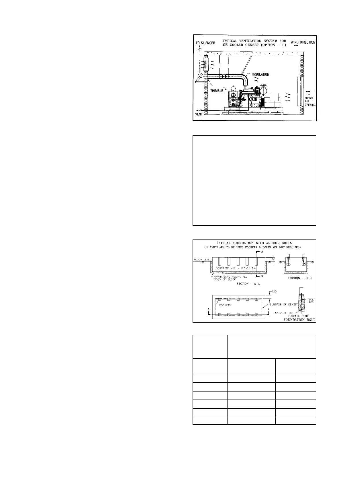
D Foundation
D.1 Do not install genset on loose sand or clay.
D.2 Foundation should be designed considering safe bearing
capacity of soil. Vibration isolators (AVMs) reduce
generator set vibration and noise transmission to the
surrounding structure. Hence they are recommended,
however they are not mandatory.
D.3 If foundation is with anchor bolts, higher depths of
foundation is required as compared to mounting on AVMs.
Please refer attached table for depths of PCC (Plain
Cement Concrete) for typical soil condition, however
structural engineer should be consulted to verify the data
depending upon soil condition. If RCC (Reinforced Cement
Concrete) is used the depth of foundation can be reduced
as per recommendation of structural / civil engineer.
Pockets (150 mm x 150 mm) are required if foundation
bolts are to be used. For AVMs plain foundation is
adequate. Static and dynamic load data for foundation
design can be furnished on request.
Ref. D.3
Typical Depth of PCC Foundation
(For soil bearing capacity
5000 kg/m 2 i.e. 1025 lb./ft.2 )
Model Without With
KVA AVM (mm) AVM (mm)
750-2000 1500 600
625 1200 400
320-500 1200 400
200-320 1000 400
Upto 200 900 400
82.5 450 200
Ref. C.5 (B)
Engine room ventilation can be estimated by the following
formulas :
H
V (cfm) = ————————— + Engine Combustion Air
0.070 x 0.24 x ∆ T
or
H
V (m
3
/min) = ————————— + Engine Combustion Air
1.099 x 0.017 x ∆ T
V = Ventilating air (cfm) (m
3
/min).
H = Heat radiation (Btu/min) (kW).
∆ T = Permissible temperature rise in engine room
(
o
F) (
o
C).
Density of air at 100
o
F = 0.070 lb/cu ft (1.099 kg/m
3
).
Specific heat of air = 0.24 btu/
o
F (0.017 kW/
o
C).
Assuming 38
o
C (100
o
F) ambient air temperture.
Ref. C.7
Ref. D.3