12
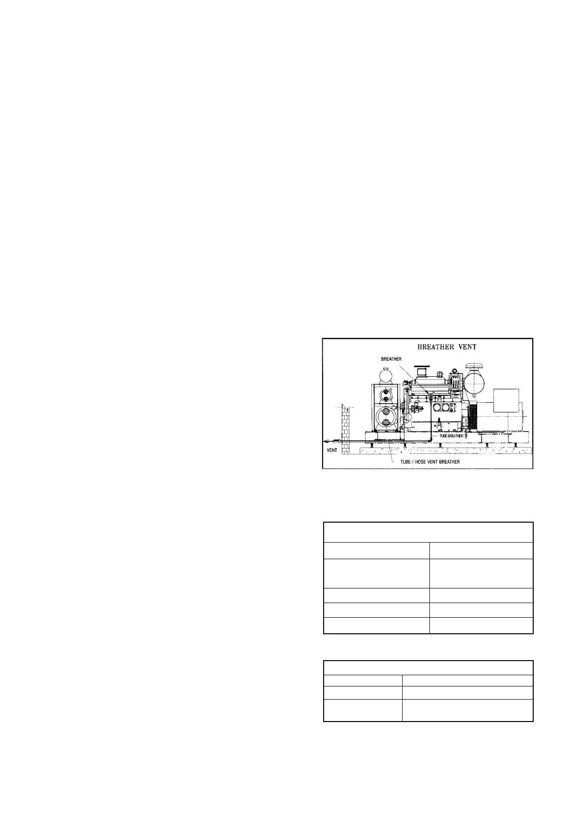
I Engine Breather Vents
I.1 Crankcase gases should be piped outside the engine
room so that oil fumes don’t accumulate on the engine/
radiator. Oil fumes affect appearance, performance of
radiator and early choking of air cleaners.
I.2 Vent tube / hose should continuously slope downwards
to avoid oil accumulation.
J Cooling System
J.1 Systems are designed for ambient temperature of 50
O
C.
J.2 Water used in cooling system should have properties
as mentioned in Table J.2. If properties are outside the
limits then it can result in
– Scale formation
– Overheating
– Corrosion
Water softening / demineralizing plants should be used,
if raw water quality is not acceptable.
Please refer Table J.2A for coolant to be used in various
engine models.
Ref. I.1
Water Properties
Hardness as CaCO3 170 ppm max
PH - Raw water 6.5-7.5
PH - Engine water 5.0-9.0
Chlorides 40 ppm max
TDS 400 ppm max
Sulphates 100 ppm max
Ref. J.2
Coolant for various engines
B/S/X Series 50-50 Water and Ethylene glycol
C Series AL Plus (DCA4) Premix
All other engines
CAC (DCA2) + Water
(Including N14)
Ref. J.2A
When engine is stopped, the gas pressure should be set to 200 mm of water column. When the engine is running
at rated load and speed, the gas pressure should be re-adjusted to 75 mm of water column.
The gas pressure before carburettor inlet is to be set to 75 to 100 mm (3 to 4 inches) of water column when engine
is running at rated load and speed.
Please ensure fluctuation free gas flow at inlet of regulator.
Care to be taken while installing the gas pipe line components
1 Ensure that the arrow is in the direction of GAS FLOW
2 After the gas line pipe welding / fabrication is complete ensure that the entire line is flushed by air. After installation
ensure no leak
3 Ensure that the gas pressure before the main line regulator (1st stage) is within 1.4 to 2 Kg/cm
2
4 Recommended pipe sizes for main line and inlet outlet diameter of regulators are listed in Table-3. Please ensure
the pipe specifications are matched
5 The schematic diagram shows typical gas pipe line. Please ensure to adopt pressure gauges between the gas
shut-off valve and first stage regulator 1.4 kg/cm
2
(20 PSIG). Also install 0.5 kg/cm
2
(7 PSIG) pressure gauge
between first stage pressure regulator and second stage pressure regulator
6 The part number details of the components used in the gas train components are given in the Table-3.