8
G.4 Exhaust piping inside the genset room should be lagged
along with aluminum sheet cladding to avoid heat input to
the room. Typical thickness of lagging is 50 mm.
G.5 Exhaust flexible shall have its free length when it
is installed. Recommended piping arrangement
with support locations for KTA19G4 engine is shown
in G-5.
For K6 and bigger engines 2 flexible bellows per bank
and residential silencer is supplied as standard scope.
For engines upto KTA1150 only one bellow is supplied.
However, if exhaust pipe length is more than 7 m then
additional bellow / provision for expansion should be
provided.
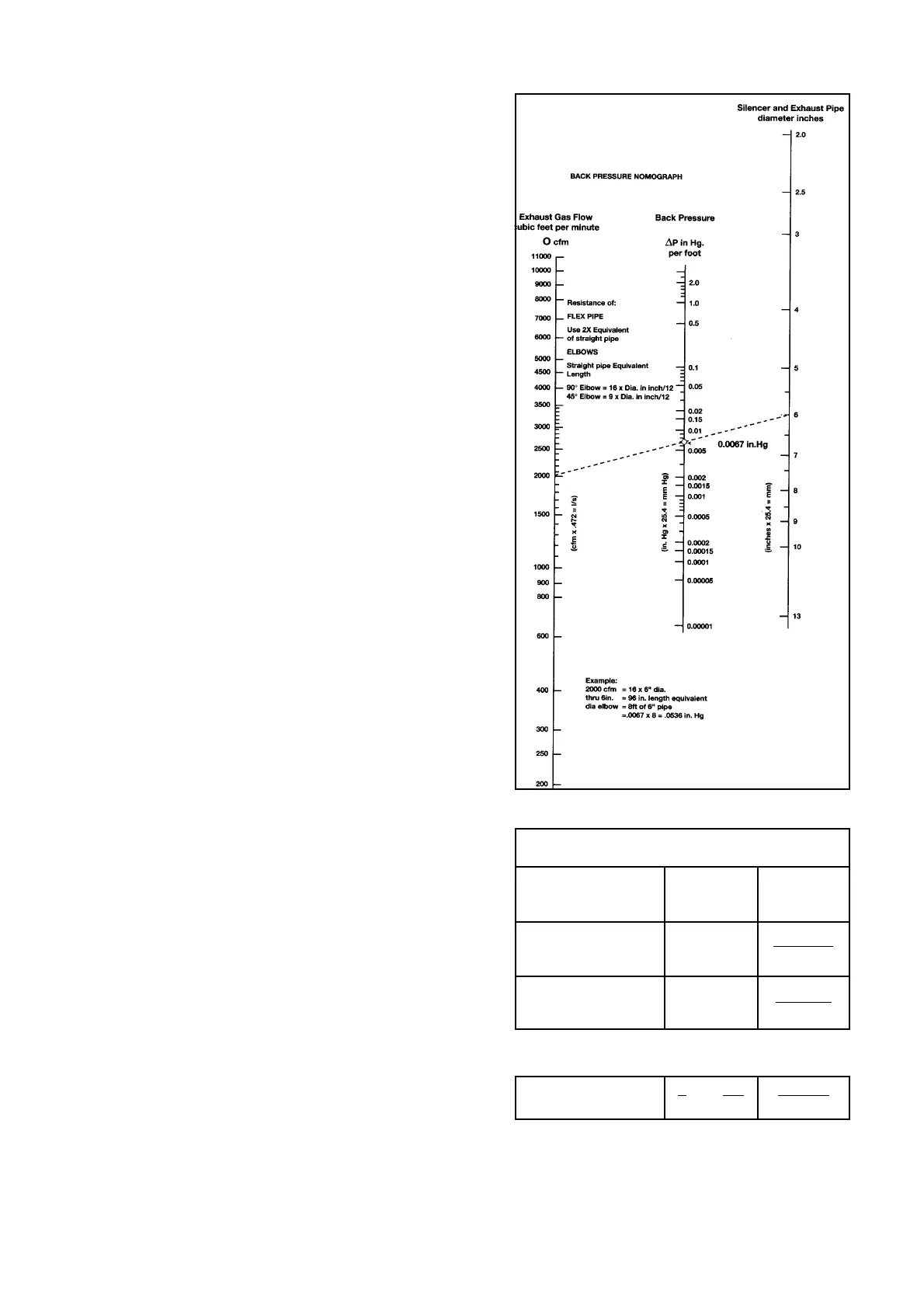
G.6 It is recommended to use ‘Schedule B’ MS pipes and
long bend elbows. Please refer Table 1 for pipe sizes.
If number of bends are more than 4 or pipe length
is more than 10 meters than contact OEM /
Cummins for piping arrangement. Please refer back
pressure nomograph for calculating exhaust piping
back pressure, if required.
G.7 The exhaust outlet should be in the direction of prevailing
winds and should not allow exhaust gases to enter air
inlet / windows etc.
G.8 There should be rain trap to avoid rain water entry. If rain
cap is used the distance between exhaust pipe and rain
cap should be higher than diameter of pipe. It is also
recommended that horizontal run of exhaust piping should
slope downwards away from engine to the condensate
trap. Silencer should be installed with drain plug at bottom.
Above covers general guidelines for exhaust system
installation. For model-wise details regarding installation
and scope of supply, please refer to service information
bulletin SIB 00-2, available with Cummins network.
G.9 Optimum Silencer Location : Location of the silencer in
exhaust system has very definite influence on both
silencing and back pressure imposed on the system. The
preferred silencer locations are given in the Table G.9,
where L is length of the total exhaust system measured
from exhaust manifold in meters. Please note that locating
the silencer as per optimum silencer location is not
mandatory. For high rise buildings suitable arrangements
may have to be provided in consultation with acoustic
engineer.
G.10 Exhaust stack height : In order to dispose exhaust
above building height, minimum exhaust stack height
should be,
H = h + 0.2 x √ KVA
Where H = height of exhaust stack
h = height of building.
Ref. G.9
Optimum Location of Silencer (in meters)
In-line ‘V’ Engine
Engine Engine
Best 2 L/5 4 L – 1.5
5
Second best 4 L/5 2 L - 4.5
5
Worst Location of Silencer
Lor3 L 3 L - 10
55 5
Ref. G.6