ASSEMBLY INSTRUCTIONS
— CONTINUED
15
15d
15e
If more reach is needed, an extra boom tube
is provided. To install, continue assembly
instructions as follows:
NOTE: The extra boom tube can be stored on the
lower half of the carriage frame and secured with
the provided locking screw.
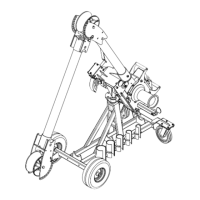
6. Remove the nose unit from the boom tube you
installed in Step #1. Slide the Model #1710 elbow
unit onto the end of the boom tube as shown in
Photo 15a. Pull the spring-loaded boom pin on
the elbow unit and fully insert the elbow unit until
it completely fills the sight hole. (See Photos 15b
& 15c). Rotate the elbow unit until the spring-
loaded boom pin locks it into the proper position
for the pull.
7. Slide the additional boom tube into the elbow
unit. Pull the spring-loaded boom pin on the
elbow unit and fully insert the additional boom
tube until it completely fills the sight hole. Rotate
the boom tube until the spring-loaded retainer pin locks it into position.
(See Photo 15d).
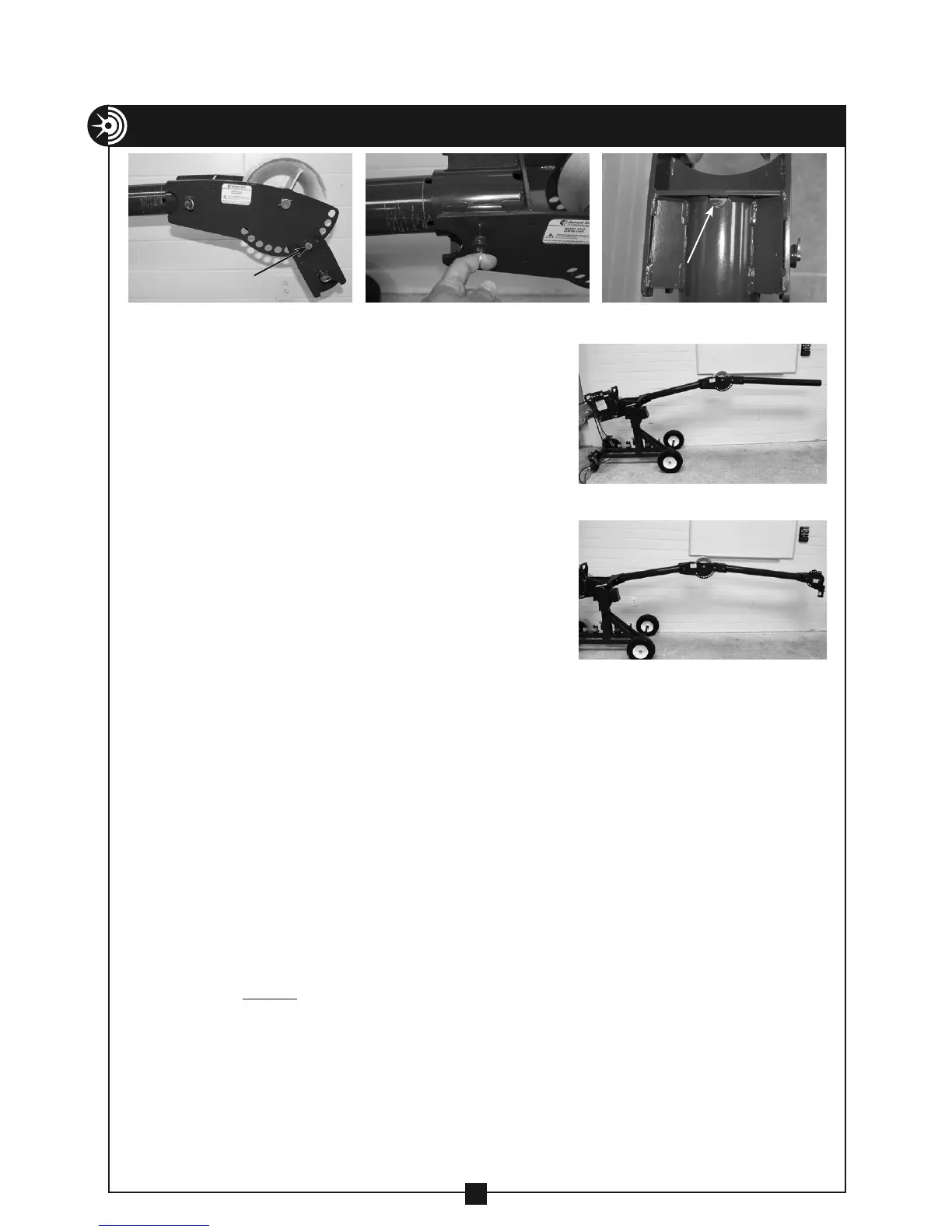
8. Refer to step #2 in the assembly instructions section and install the model #1840-S
nose unit (or #1840 optional nose unit) on the end of the additional boom tube
(see photo 15e).
9. If angle adjustment is needed, remove the spring clip from the elbow unit angle
adjustment pin, remove the pin and adjust the angle to the desired degree. When the
correct angle is achieved, re-insert the pin and secure with the spring clip.
10. You are now ready to pull cable.
11. If more reach is required, both the 3' and 4' lengths of factory supplied boom tubes
may be replaced with up to 10' lengths of 3" rigid conduit or 3" schedule 40 pipe. ONLY
use 3" rigid conduit or 3" schedule 40 pipe for boom tubes. NEVER substitute any other
size or type of conduit or pipe for boom tubes. NEVER replace factory supplied boom
tubes with shorter boom tubes.
NOTE: The weight of boom sections longer than the factory supplied booms will
require manual assistance to use the boom height adjustment handle.
IN ADDITION, screw-on couplings may be necessary to support the boom and
prevent it from falling.
15b 15c
Sight Hole
15a
Elbow Unit Angle
Adjustment Pin