The CURT Reflex Brake Control is an electronic brake control module designed for use with 12-volt negative ground systems and trailers equipped with two to eight brakes. This installation and user guide provides comprehensive instructions for mounting, wiring, calibration, and troubleshooting the device.
Function Description:
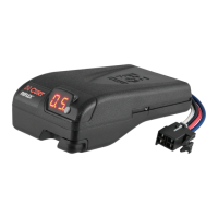
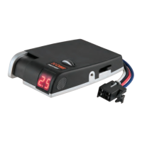
The Reflex Brake Control is a proportional brake controller that senses the tow vehicle's deceleration and applies the trailer brakes with a proportional force. This ensures smooth and controlled braking, enhancing safety while towing. It features a digital display for communicating operating errors and current settings, a load range/calibration button, an output adjustment thumb wheel, and a manual control lever. The manual control lever allows for independent activation of the trailer brakes, which can be useful for testing or in situations where the tow vehicle's brakes are not engaged. The device is designed to work with most electrically activated hydraulic trailer brake systems.
Important Technical Specifications:
- Compatibility: 12-volt negative ground systems.
- Brake Capacity: Suitable for trailers with two to eight brakes.
- Power Conservation: Enters a power conservation mode after one hour of inactivity and wakes when the brake pedal is pushed.
- Polarity Protection: Protected against positive and negative power reversal, preventing damage from incorrect wiring.
- Mounting: Nearly unlimited mounting positions, but must stay within 20° horizontally.
- Circuit Breaker: Requires a 30 amp, auto-reset circuit breaker mounted as close to the battery as possible.
- Wiring: Utilizes 10 gauge wires for power and ground connections to the battery, a 10 gauge blue wire for the trailer brake terminal, and a red wire for the stoplight switch.
Usage Features:
- Digital Display: Provides real-time feedback on the device's status, including sleep mode (blank screen), no trailer connected (one dot), trailer connected (two dots), manual control activated with no trailer (O.C), and brake activation with output reading (0.5 to 0.9).
- Calibration: A single calibration is required upon initial setup. This is performed by pressing and holding the load range/calibration button on a level surface with no brakes applied until 'CL' appears on the display. The calibration mode is locked out when brakes are engaged to prevent inadvertent calibration. Recalibration is necessary if the module loses power, the mounting angle changes, or 'CL' flashes.
- Load Range Setting: The load range can be adjusted using the load range/calibration button to match the trailer's Gross Vehicle Weight (GVW) relative to the tow vehicle's GVW. Options include:
- L1: Trailer GVW is less than tow vehicle GVW.
- L2: Trailer GVW is approximately equal to tow vehicle GVW.
- L3: Trailer GVW is up to 50% more than tow vehicle GVW.
- L4: Trailer GVW is more than 100% greater than tow vehicle GVW.
- Output Adjustment: The output adjustment thumb wheel allows for fine-tuning the braking force. Initial setup involves sliding the manual control lever fully to the left while the engine is running and the trailer is connected, then adjusting the output wheel until "5.0" is displayed.
- Manual Control Lever: Activates the trailer brake lights and allows for independent application of trailer brakes.
- Reduced Output: Provides reduced output when the vehicle is stationary (e.g., at a railroad crossing or stoplight) to prevent unnecessary wear on trailer brakes.
- Error Communication: The digital display is capable of communicating operating errors such as a single dot when the brake pedal is pushed with no trailer connected, flashing O.C for manual control activated with no trailer, flashing S.C for a short circuit in the blue brake wire circuit, and C.S for low or no power from the tow vehicle's battery.
Maintenance Features:
- Troubleshooting Guide: The manual includes a troubleshooting guide that explains various display indicators and their corresponding issues, aiding in self-diagnosis.
- Bench Test: A detailed bench test procedure is provided to confirm proper function of the brake control module outside of the vehicle. This involves connecting the module to a 12V battery and an 1156 automotive bulb, then performing a series of steps to verify display readings and bulb illumination. This test helps identify if the unit itself is faulty before extensive vehicle wiring checks.
- Wiring Diagram: A clear wiring diagram is included to assist with correct installation and troubleshooting of electrical connections. It emphasizes direct connections to the battery for positive and ground, and provides special instructions for specific Ford vehicle models regarding stoplight switch connections.
The CURT Reflex Brake Control is designed for ease of installation and reliable performance, with features aimed at user convenience and safety during towing operations.