Curtis 1232E/34E/36E/38E & 1232SE/34SE/36SE Manual, os 30
3
24 NOVEMBER 2015
2 — INSTALLATION & WIRING
2
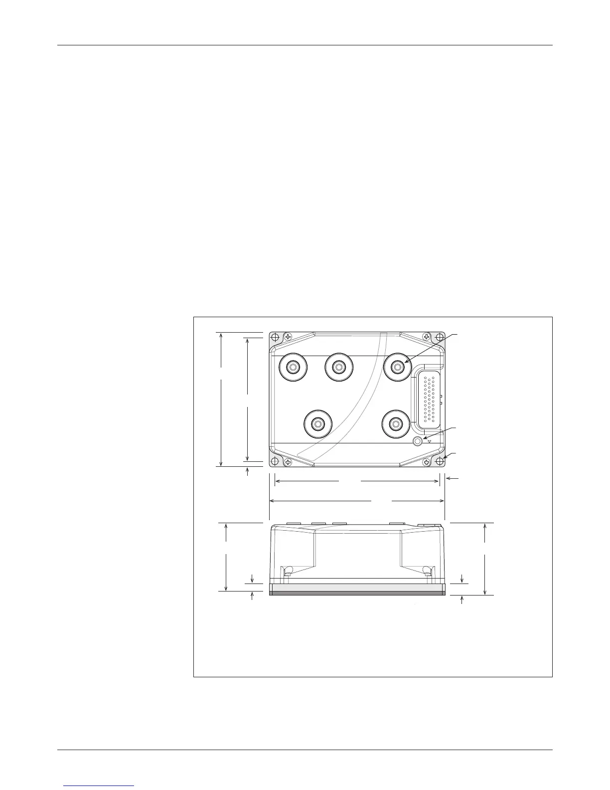
Fig. 2a Mounting dimensions,
Curtis 1232E and 1232SE
motor controllers.
Note: The SE has a thicker base.
Dimensions in millimeters.
INSTALLATION AND WIRING
MOUNTING THE CONTROLLER
e outline and mounting hole dimensions for the 1232E/SE controller are shown in
Figure 2a, for the 1234E/SE controller in Figure 2b, and for the 1236E/SE and 1238E
controllers in Figure 2c. When an Ampseal plug housing is mated with the
35-pin logic receptacle, these controllers meet the IP65 requirements for envi-
ronmental protection against dust and water. Nevertheless, in order to prevent
external corrosion and leakage paths from developing, the mounting location
should be carefully chosen to keep the controller as clean and dry as possible.
It is recommended that the controller be fastened to a clean, at metal
surface with four 6 mm (1/4") diameter bolts, using the holes provided. A thermal
joint compound can be used to improve heat conduction from the controller
heatsink to the mounting surface. Additional heatsinking or fan cooling may
be necessary to meet the desired continuous ratings.
B
-
U
71
169
180
5.5
∅7.0 thru, 4 plcs
140
129
5.5
V
W
B
+
8
Status LED
window
1232E
75
12
1232SE
M6 x 1.0, 5 plcs