4
Curtis 1268 Manual, Rev. D
INSTALLATION AND WIRING
MOUNTING THE CONTROLLER
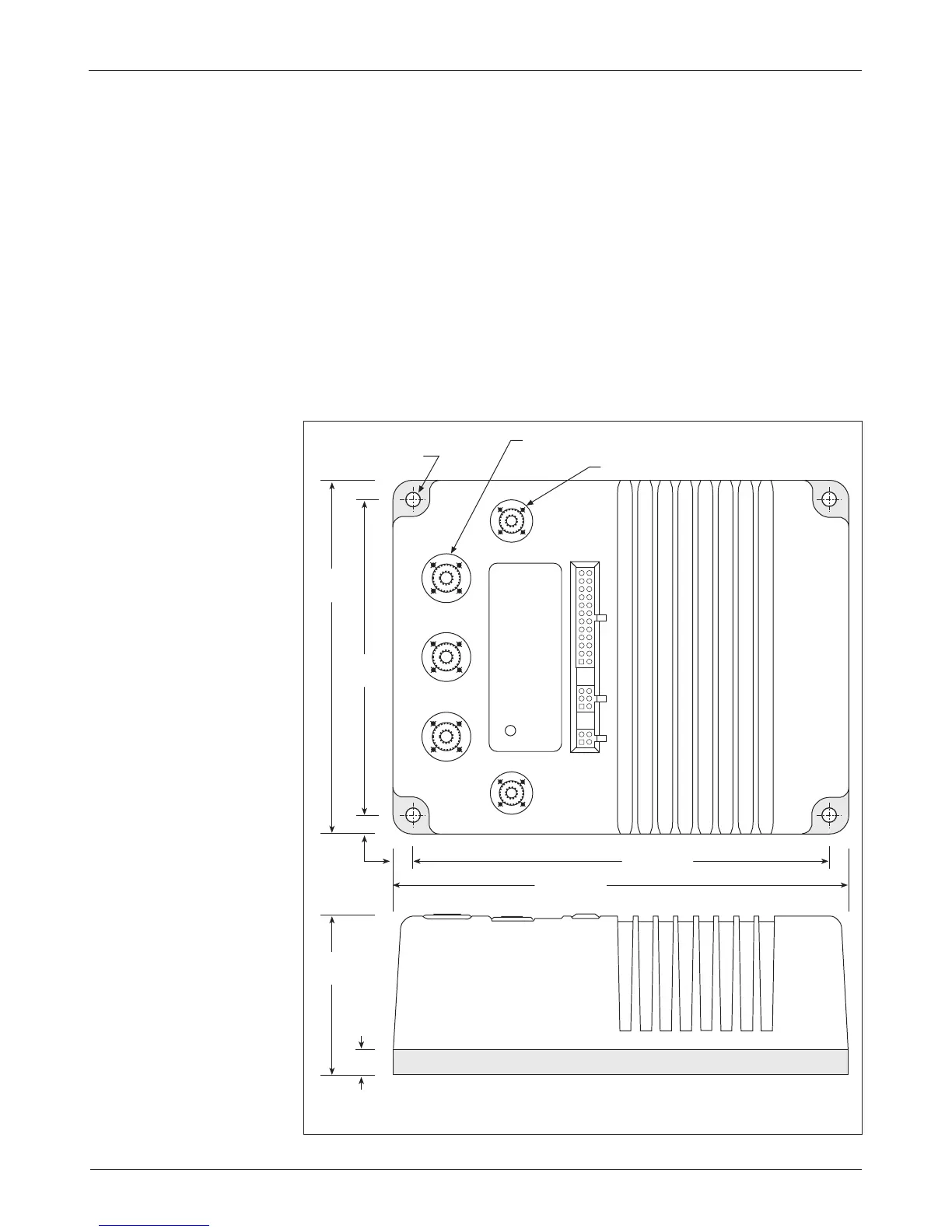
The outline and mounting hole dimensions for the 1268 controller are shown
in Figure 2.
The controller can be oriented in any position, and meets the IP64/IP67
ratings for environmental protection against dust and water. However, the lo
-
cation should be carefully chosen to keep the controller as clean and dry
as possible
. When selecting the mounting position, be sure to also take into
consideration (1) that access is needed at the top of the controller to plug the
programmer into its connector, and (2) that the built-in Status LED is visible
only through the view port in the label on top of the controller.
Fig. 2 Mounting
dimensions, Curtis
1268 controller.
Dimensions in millimeters (and inches)
2 — INSTALLATION & WIRING: Controller
2
9.5
(0.375)
12.7
(0.50)
STATUS
LED
M8 thread, 3 plcs
M6 thread, 2 plcs
7.1 (0.28) dia.,
4 plcs
159
(6.25)
178
(7.00)
81
(3.19)
210 (8.25)
229 (9.00)