6
Curtis 1268 Manual, Rev. D
CONNECTIONS
Low Current Connections
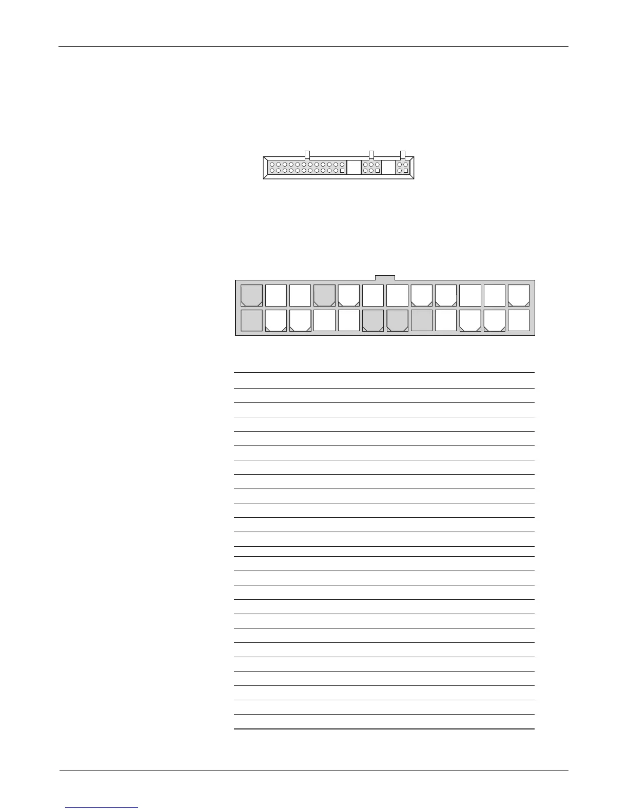
Three low current connectors are built into the 1268 controller. They are
located in a row on the top of the controller:
J1-1 Keyswitch Input (KSI) input and return for main contactor coil
J1-2 Logic Enable input from run/store switch
J1-3 Fuse Sense input from WalkAway™ fuse sense line
J1-4 Logic Power power to controller logic
J1-5 (not used) —
J1-6 (not used) —
J1-7 (not used) —
J1-8 Pedal Interlock Switch input from pedal switch, wired to throttle
J1-9 WalkAway™ Return coil return for WalkAway™ relay
J1-10 Forward input from forward switch
J1-11 Reverse input from reverse switch
J1-12 (not used) —
J1-13 Pot High +5V supply through 453
Ω
(or ITS input)
J1-14 Pot Low 453
Ω
to ground
J1-15 Pot Wiper throttle wiper input (or ITS input)
J1-16 LED Ground ground for external LED
J1-17 Main Contactor contactor coil driver low-side output
J1-18 Brake Light Driver relay driver low-side output
J1-19 Reverse Alarm alarm low-side driver output
J1-20 Mode Switch input from mode switch
J1-21 (not used) —
J1-22 External LED Driver LED driver high-side output
J1-23 Auxiliary Driver WalkAway™/EMB driver low-side output
J1-24 (not used) —
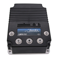
The 24-pin connector provides the logic control connections. The mat-
ing connector is a 24-pin Molex Mini-Fit Jr. connector p/n 39-01-2245 using
type 5556 terminals. The appropriate wire gauge is 18–24 AWG.
2 — INSTALLATION & WIRING: Controller
J1 J2 J3
J1 Logic connector
J2 Speed Sensor connector
J3 Programmer connector
24 23 22 21 20 19 18 17 16 15 14 13
12 11 10 9 8 7 6 5 4 3 2 1
J1