Curtis 1030 Acuity Manual, Rev. C
3
2 — INSTALLATION & WIRING
2
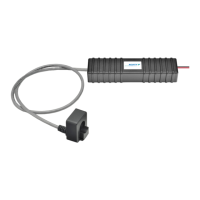
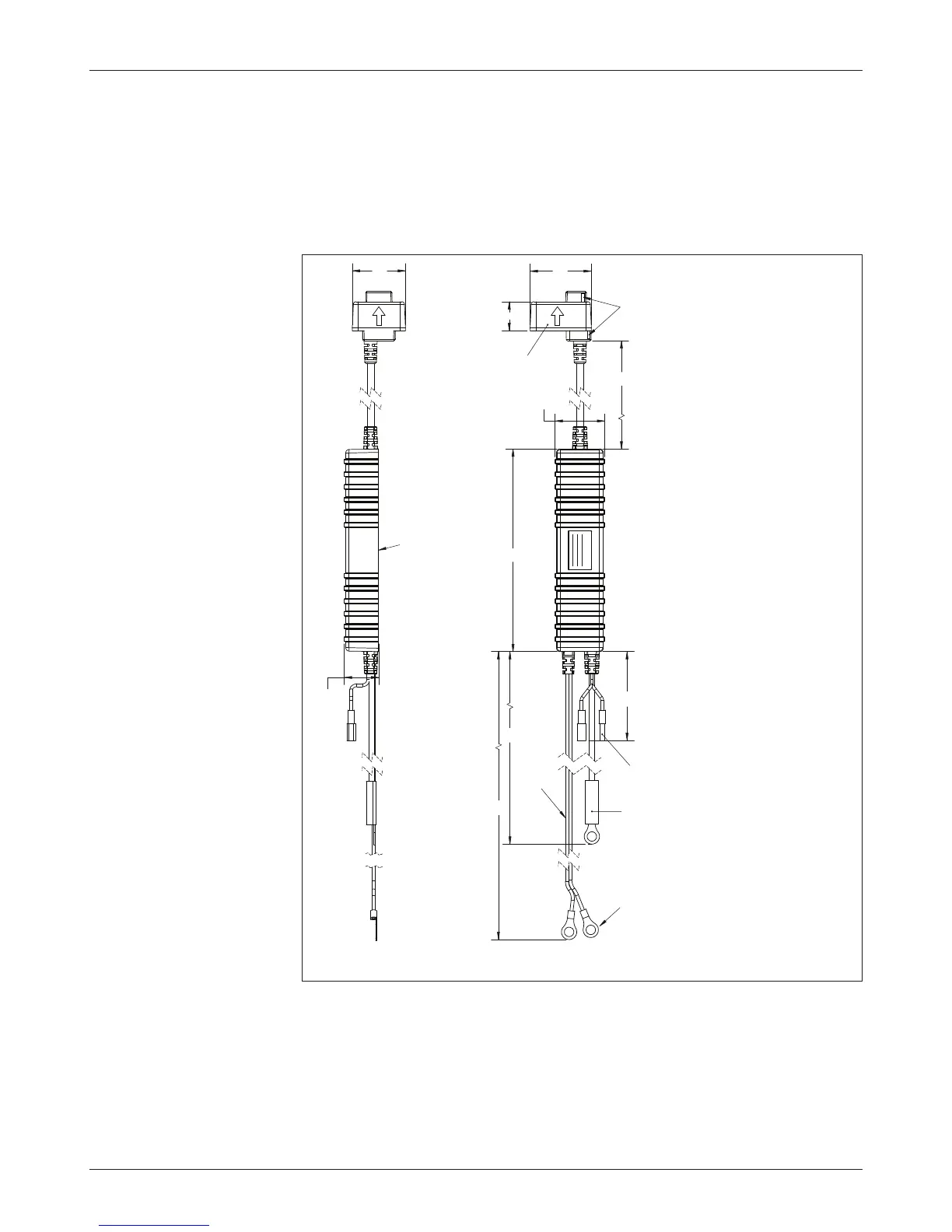
Fig. 2 Mounting
dimensions, Curtis 1030
Acuity.
INSTALLATION AND WIRING
The outline and dimensions for the 1030 Acuity are shown in Figure 2.
Perform the installation in an area that is well ventilated. Before
installing the Acuity module, clean the battery, cables, and terminals.
Dimensions in millimeters
DIMENSI ONS m m
MOD E L 1030
5/16" RING
TERMINALS
TYP 3X
ALLOWABLE
MENISCUS
3mm MAX
CAN CONNECTOR
Pin 1 & Pin 2
TEMP SENSOR
CABLE
960±15
605±15
125±15
940±15
179
30
SEE NOTE 2
CURRENT SENSOR
Arrow shows direction
of discharge current
44
54
POWER
CABLES
B+ : Red
B– : Black
26
47
NOTES:
1. Case & Current Sensor Housing
Material: Glass-lled PBT.
2. Current Sensor can accomodate
most cable sizes up to 4/0.
3. Current Sensor to be held to
battery cable by tie-wraps
(2 places).
4. Acid resistant tie-wraps should
be used to secure unit.
5. This unit not tted with a CAN
termination resistor.
CAN CONNECTOR
PIN 1: CAN Hi — White Mates
with Molex 19038-0001.
PIN 2: CAN Low — Black mates
with Molex 19034-0005.
 Loading...