4
Curtis 1030 Acuity Manual, Rev. C
Connecting B+, B–, and the temperature sensor
The Acuity’s B+, B–, and temperature sensor connections are made via 5/16"ring
terminals. Simply place the ring terminal over the battery stud/terminal and
then replace the washer and nut.
Installing the current sensor
The current sensor is polarity sensitive and must be properly oriented for the
Acuity to work correctly.
2 — INSTALLATION & WIRING
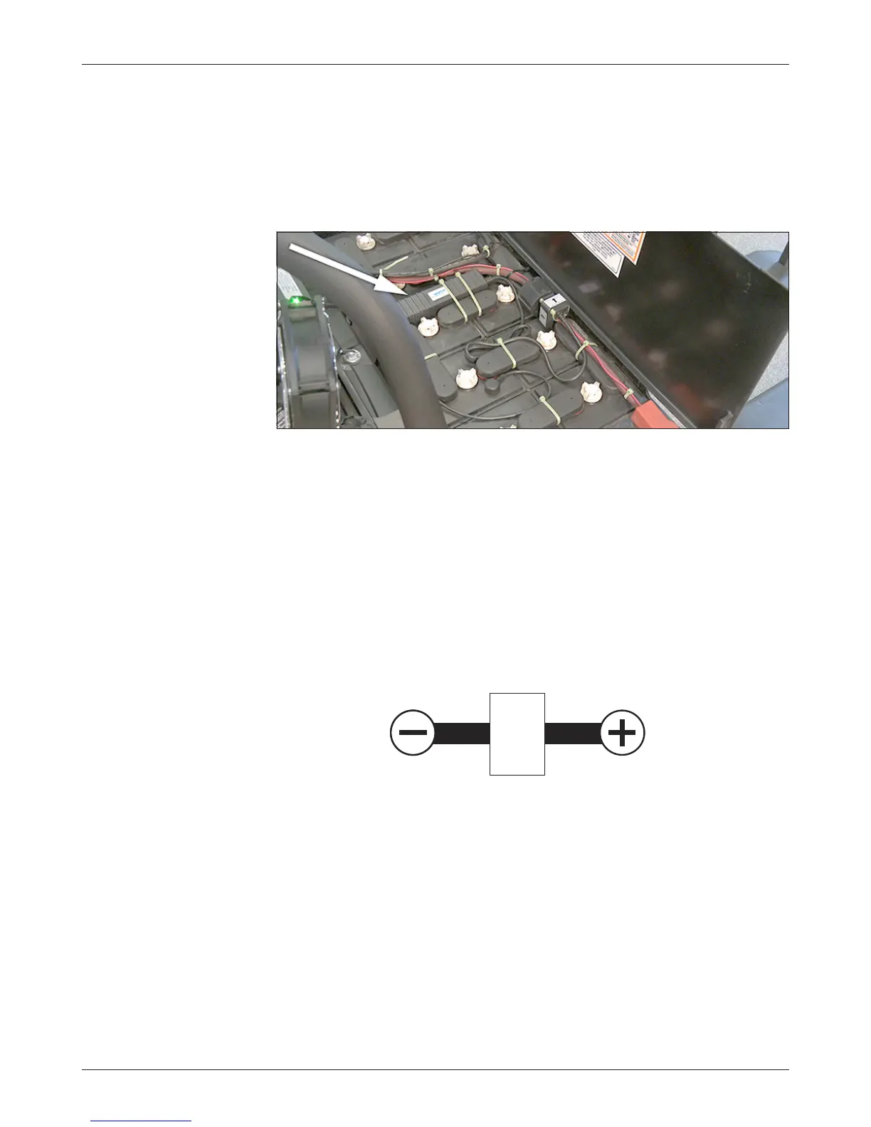
Fig. 3 Typical installation,
showing batteries with
Acuity installed.
«
– +
– +
– +
– +
NEGATIVE
TERMINAL
POSITIVE
TERMINAL
CURRENT
SENSOR
Either B+ or B– can be selected to pass through the current sensor, de-
pending on the battery configuration and location of the current sensor.
Pass the end of the battery cable through the opening of the current
sensor, making sure that the marking on the current sensor is pointing in the
correct direction.
Insert a tie wrap into each of the slots in the current sensor and pull the
battery cable tight against the side of the current sensor in which the slots are
located.
Mounting the Acuity module
Locate the Acuity module on the battery in such a way as to avoid damage to
the Acuity through normal battery/vehicle use. Use acid-resistant tie wraps to
secure the Acuity to the battery using the intercell connectors and the ribs that
are molded into the Acuity module; see Figure 3.
 Loading...