10 AXN Quick Start Kit User Guide (BK/0045 | 9 Aug. 2021)
2
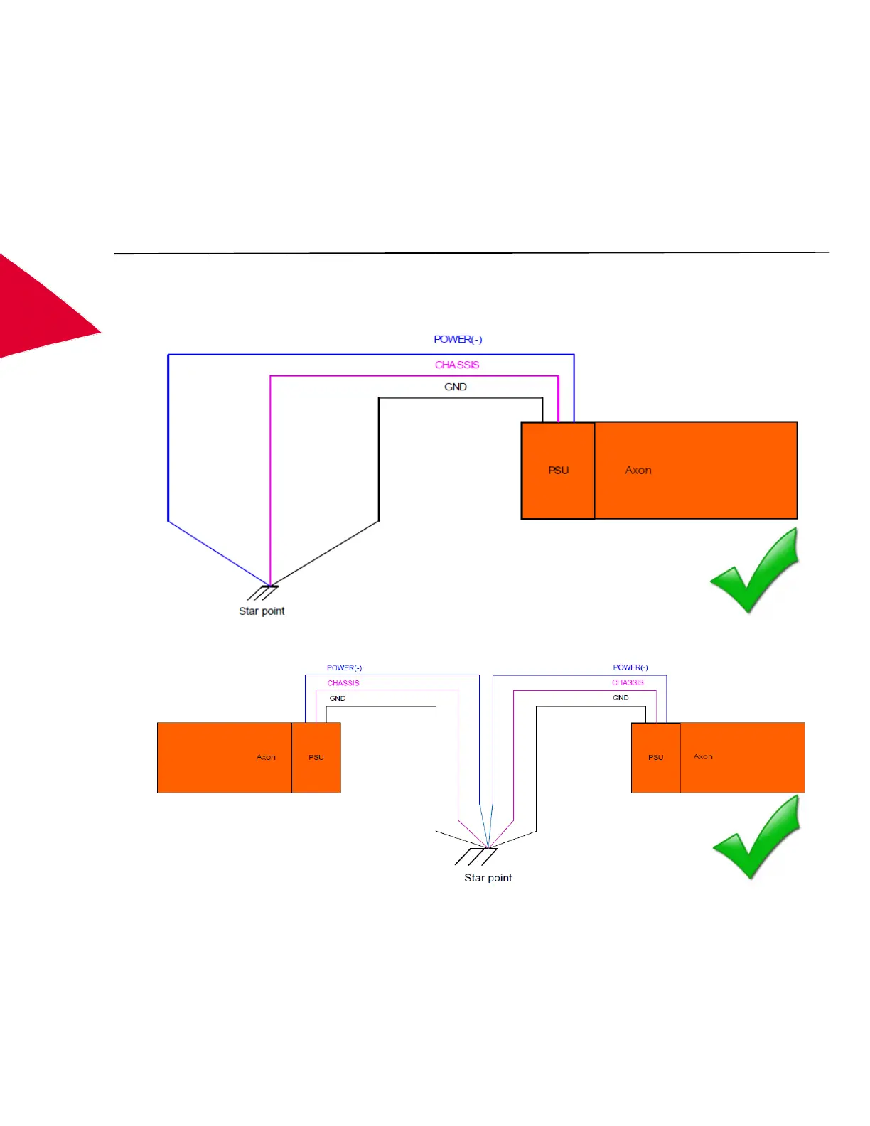
AXN grounding
Each isolated ground signal should be connected to the main star point on the aircraft or vehicle using a low
impedance connection.
Hence the GND pins on the AXN PSU connector, and the POWER (-) pin on the PSU connector should be
connected directly to the star point.
It is acceptable to use the ground mounting bolt on the PSU instead of the CHASSIS pin.
A common cable should not be used to take more than one of these signals to the star point.
NOTE: When more than one AXN is used, each AXN should be connected to the star point using individual cables.
Shared cables should not be used.
Figure 9: Axon product family grounding
Figure 10: Grounding for multiple chassis
Validating grounding
After connecting the grounds, measure the resistance between each GND point, CHASSIS point and POWER (-)
on each AXN to the star point. The resistance should be below 50 mΩ.