9
#7-ASSEMBLYOF12 AND
15METERSSTUBS
KEY P/NDISPLAY DESCSIZEQTY
3” (7.6 cm
)
INSERT
SB R8SB R8STUBSB 1/4"x6" 4
(.6x15cm)
105 055105 BLACKPLASTIC 1/4" 2
CAP (.6cm)
407 030407 SSWORM 7 /32"-5/8" 6
CLAMP (1.2x1.6cm)
SF R8SF R8STUBSF 3/8"x72" 2
(1x182.9cm)
SH R8SH R8STUBSH 3/8"x68" 1
(1x173cm)
SG R8SG R8STUBSG 3/8"x43-1/2" 1
(1x110.5cm)
3” (7.6 cm)
INSERT
407
407
SG
SH
SF
SF
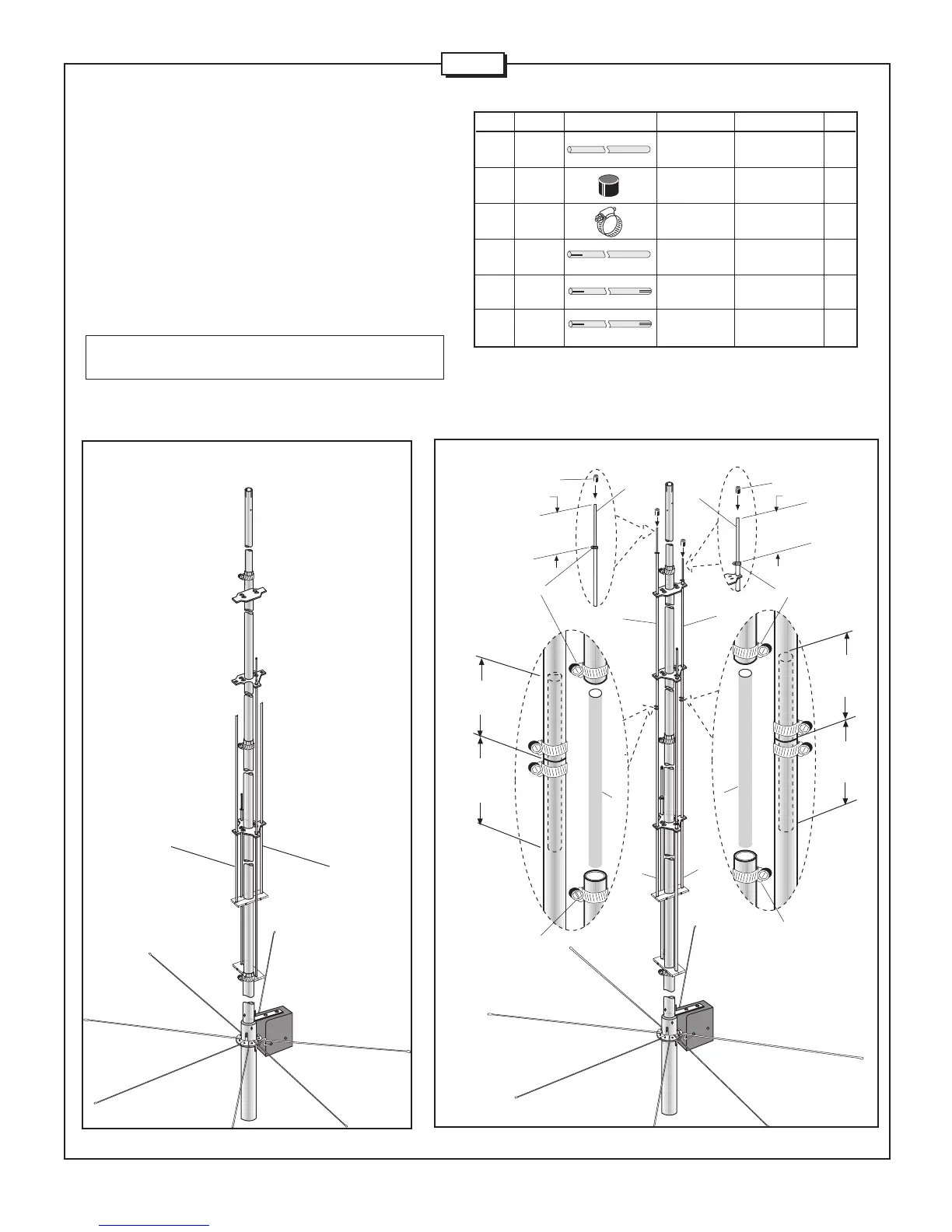
FIGUREJ1
FIGUREJ2
Take two tubes (SF) and slide them through 4-hole plastic insulator
and secure in top stub clamp as shown in Fig. J1. Insert two
6"rods (SB) in (SF) tubes and place the worm clamps (407) as
shown in callout at Fig. J2. Place tube (SH) on left side stub as
shown in Fig. J2, sliding it through 2 and 3 hole plastic insulators.
Insert tube (SG) on the right side stub as shown and secure with
worm clamp. Take two (SB) rods and insert them on top of these
two stubs as shown in top callouts of Fig. J2 along with protective
end caps.
Note: Make sure that all stubs are positioned around main radiator
as shown in Fig. J2
407
407
SF
SF
3-1/2” (8.9 cm)
EXPOSED
3” (7.6 cm)
INSERT
3” (7.6 cm)
INSERT
3-1/2” (8.9 cm )
EXPOSED
105
105
SB
SB
SB
SB
R9
 Loading...