BA
3
#1-ASSEMBLERADIAL
RINGS
232
232
87
87
428
73
232
232
232
232
87
87
87
87
87
96
87
96
87
87
79
74
73
79
73
FIGURE
D
FIGURE
A
FIGURE
C
FIGURE
B
73
73
BA BASE 1
ASSEMBLY
BRACKET
74 194174 RADIAL RING 2
79 010079 SS MACHINE # 8-32 x 1/2"
4
SCREW (1.3 cm)
87 014387 SS LOCK # 8-32 14
NUT
232 010232 SS MACHINE # 8-32 x 2-1/2" 6
SCREW (6.35 cm)
428 902428 Radial Ring 1
Connector
KEY P/N DISPLAY DESC. SIZE QTY
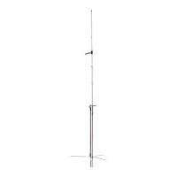
N to e:
RadialRingmountsonlowestsetofholes
onthebaseinsulatorr
SeefigureD
73 194173 RADIAL RING 4
96 010096 SS MACHINE #8-32 x 3/8"
4
SCREW (.95 cm)
R9
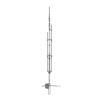
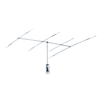
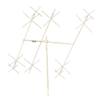
Figures A throughDshowthestepsforradialringassembly.Refer
tothepartstablebelowforthepartsrequiredinthisstep.Slide
thetworadialrings(74)ontothebaseassembly(BA).Notethe
orientationoftheringslots. Attachtheringstothebaseusingthe
radialringbrackets(73),21/2"screws(232),1/2"screws(79)
andlocknuts(87).LeavehardwarelooseuntilStep#2.Notethe
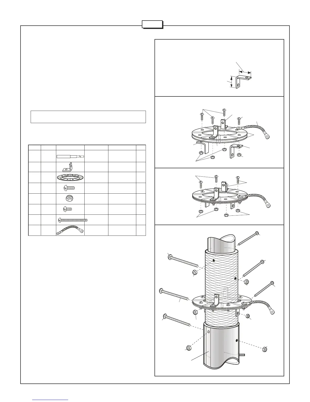
properorientationoftheradialringbracketsinFigure A.Install
groundstrap(428)asshowninFigureD.
NOTE:Donotaccidentallyusethe#10-24nutin
thisstep.
Insertfour21/2"screws(232)intothebaseassembly(BA)as
showninFigureD.Securewithnuts(87).
Longerdimension
attachestobase.
Shorter
dimension
attachesto
radialring.
428
428