Custers Hydraulica B.V. Venray NL
26-mrt-
20 www.custers.nl
16
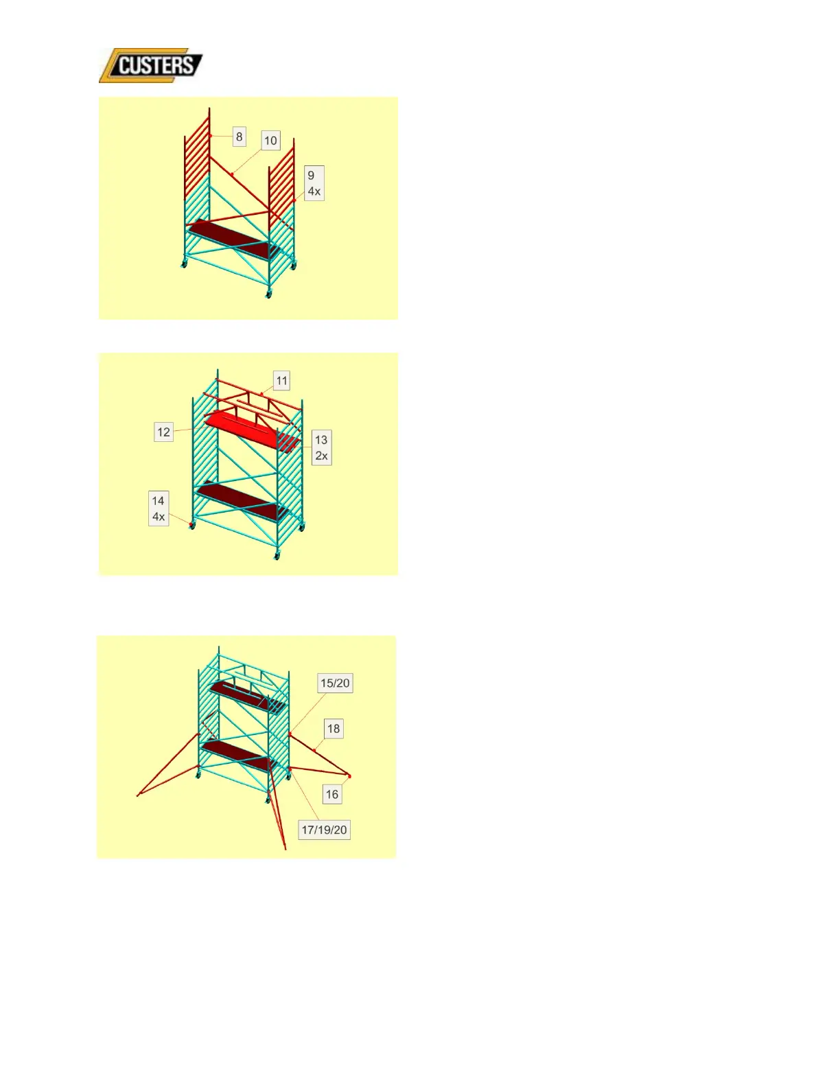
Fig.26
Fig.27
Fig.25
8: Place both 8-rung frames;
9: Place locking pins between the
frames themselves;
10: Place both diagonal ledgers;
11: Place both Safe Guard guardrail
frames on the upper rung: one to
façade side and the other in the
middle and click the diagonal ledgers
in place on the 5
th
rung of the frame in
question;
12: Place the platform with hatch to façade
side (on the 5
th
rung from the top);
13: Slide both blow-away protections
under the rung;
14: Lock the brakes and set the
scaffold level by twisting the
spindle nut of the casters;
Now place the four (large or small)
outriggers:
15: Place the upper coupler under the 6
th
or
7
th
rung at the small leg, 9
th
or 10
th
rung at the large leg;
16: Put the foot on the ground with
observance of the designated basic
form (see 4.4);
17: Make sure that the lower coupler falls
between two rungs;
18: Rotate the leg in such a way that the
designated basic form (see 4.4) is
maintained;
19: Tighten the lower coupler by hand on
the upright and slide the coupler
upwards over the upright so that the
leg is slightly tensioned;
20: Slightly tighten both couplers;