16
RS232/TTL SERIAL INTERFACE
Molex male connector 53261 series (90°)
J4
1
RT
2
TX
During transmission, takes the values -VRS232 and +VRS232 depending on data
3
RX
During reception, takes the values -VRS232 and +VRS232 depending on data
4
GND
5
EXT-PUSH
6
EXT-LEDV
Given the presence of the RS232 standard, logic value “0” corresponds to the voltage value +VRS232 (voltage value be-
tween +3Vdc and +15Vdc) and logic value “1” corresponds to the voltage value -VRS232 (voltage value between -3Vdc
and -15Vdc.
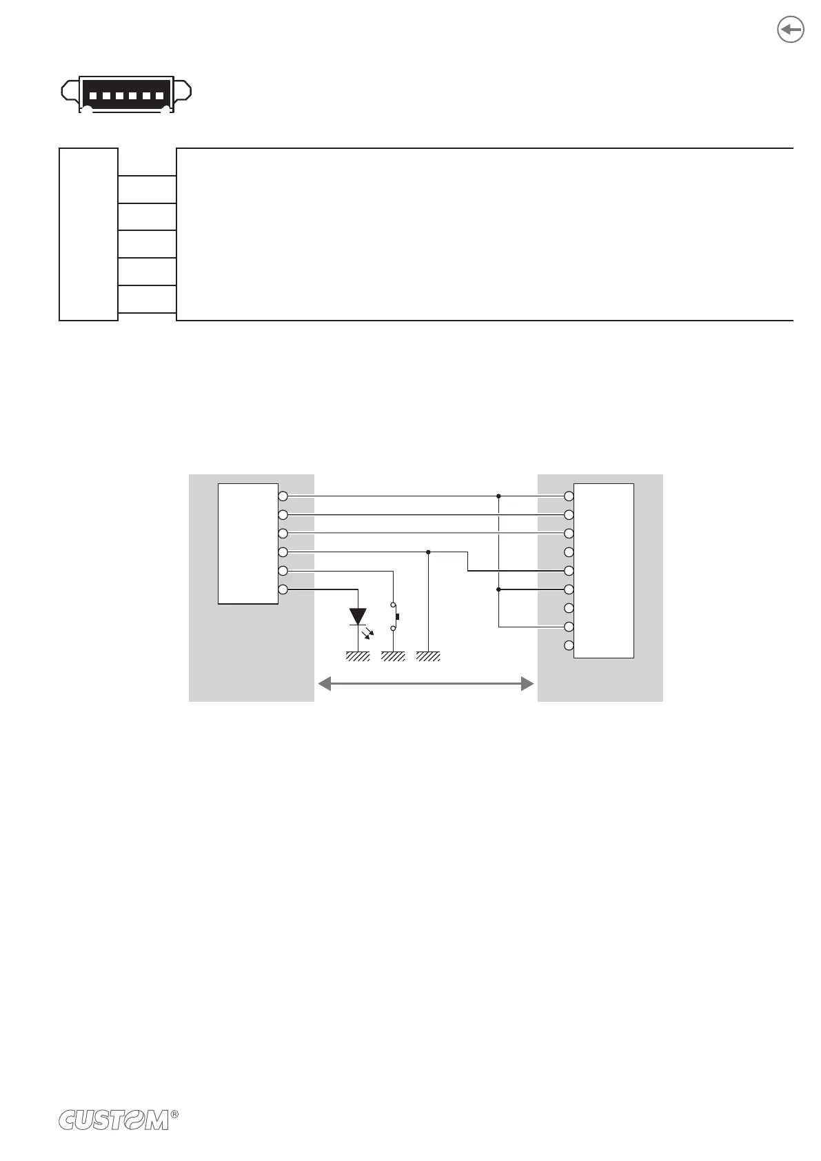
The following picture shows an example of connection between the device and a personal computer using a connector 6
pin female and a 9 pin RS232 serial connector:
DEVICE PC
1
2
DB9
1
2
3
4
5
6
7
8
9
J4
1
2
3
4
5
6
DTR DTR
TX RX
RX
GND
FEED
LED
TX
GND
When use a serial cable, we recommend the installation of a ferrite core on the power supply cable.
27