Copyright © 2011 CyberPower Systems, Inc.
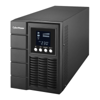
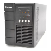
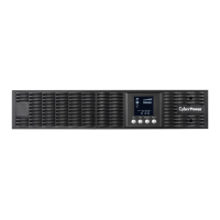
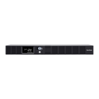
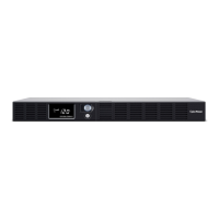
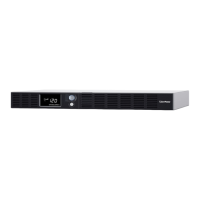
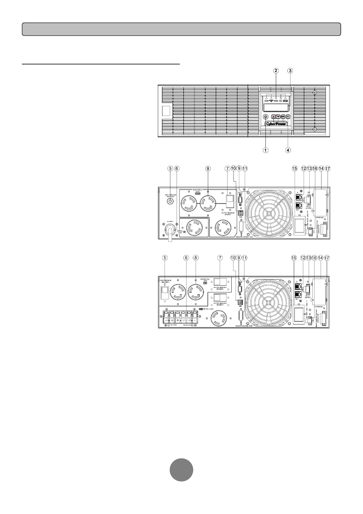
POWER MODULE FRONT/REAR PANEL DESCRIPTION
1. Power Button / Power on Indicator
Master ON/OFF for the UPS. Indicates that the UPS is on
and supplying power.
2. UPS Status / Fault / Replace Battery LED Indicator
Indicates the status of the UPS whether is operating in
Line, Battery or Bypass Mode, or the UPS has an internal
fault and the battery need to be replaced.
3. Multifunction LCD Readout
Shows UPS status, information, settings and events.
4. Function Buttons
Scroll up, scroll down, select and cancel LCD menu.
5. Input Circuit Breaker
Provides input overload and fault protection.
6. Power Cord (OL6K) / Input / Output Terminal Block
Connect to utility power / your equipment.
7. Output Circuit Breaker
Provides output overload and fault protection.
8. Battery Backup & Surge Protected Outlets
Provides battery backup and surge protection. They
ensure power is provided to connected equipment over a
period of time during a power failure.
Critical / Noncritical Load
Allows the creation of load priorities to ensure that battery
power reserves are transferred to specified outlets during
a power outage. The unit can be programmed to provide
additional runtime for equipment connected to the
“CRITICAL” outlets, while stopping the power supply to
equipment connected to “NONCRITICAL” outlets after a
designated period of time.
9. Serial Port
Serial port provides communication between the UPS and
the computer. The UPS can control the computer’s
shutdown during a power outage through the connection
while the computer can monitor the UPS and alter its
various programmable parameters.
10. USB port
This is a connectivity port which allows communication
and control between the UPS and the connected computer.
It is recommended to install the PowerPanel® Business
Edition Agent software on the PC/Server connected with
the USB cord.
11. Remote Control Port
Connects to remote LCD module to the UPS.
12. Surge Protected Communication Ports RJ-45/RJ-11
These ports are used to protect standard RJ-45/RJ-11
based products (ADSL, LAN, Phone/ Modem-Lines) and
cabling systems from surges.
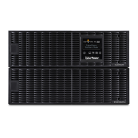
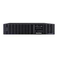
OL6KRT3UPM / OL8KRT3UPM / OL10KRT3UPM
OL6KRT3UPM
OL8KRT3UPM / OL10KRT3UPM
13. Relay Output Connector
Convert UPS signals into real potential-free Dry Contacts for industrial control.
14. SNMP/HTTP Network slot
Slot to install the optional SNMP card for remote network control and monitoring.
15. Extended Runtime Battery Module Connector
Connection for additional CyberPower XL Battery modules.
16. EPO (Emergency Power Off) Connector
Enables an emergency UPS Power-Off from a remote location.
17. Backfeed Protection Connector
Prevents power feedback from the inverter to utility power in case of power failure and a
fault in the bypass circuit.