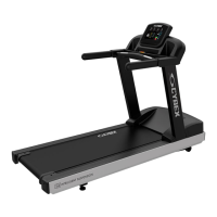
Assembly
Component and Hardware List
Components
QtyDescriptionItem
1Left Upright1
1Right Upright2
1Ergo™ Front Crossbar3
1Upper Dashboard Tray4
1Lower Dashboard Tray5
1Console6
2End Cap Front7
2End Cap Rear8
1Bridge9
1Console10
2Ergo™ Bar Backing Plate11
2Cable Tie12
Hardware
QtyDescriptionItem
8Bolt, 3/8 x 5” Hex Head1
8Washer, 3/8” Flat2
6Lock Nut, 3/8”3
8Bolt, M8 x 20mm Hex Head4
12Washer, M85
8Lock Nut, M86
2Plastic Grommet7
14Screw, M4.2 x 19mm Phillips Head8
4Screw, M5 x 25mm Phillips Head9
2Screw, #10 x 0.5” Phillips Head (silver)10
2Screw, #10 x 0.5” Phillips Head (black)11
Page 15 of 31

 Loading...