6
CONTOUR
®
ELECTROL
®
INSTALLATION FOR 120V SCREENS
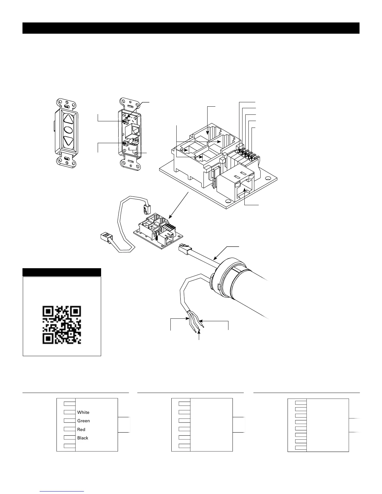
RJ-45
Receptacle
RJ-22
Output
RJ-22
Inputs
Up (Dry Contact)
Down (Dry Contact)
Common (Both)
Bus (Bus)
5V (Bus)
Front of
Wall Switch
Bus
BUS
COM
5V
LED
Up Limit
T
actile Button
Down Limit
Tactile Button
Back of
Wall Switch
CONTOUR
®
ELECTROL
®
INSTALLATION FOR 120V SCREENS
RJ-22 Pin-Outs (Tab Is Facing Up)
Standard RJ-22 can be used in place of RJ-14 cable
Bus (RP Data)
+12V
RQ Clock
RQ Data
+5V
Ground
Yellow
Green
Red
Black
White
Blue
RJ-45 Pin-Outs (Tab Is Facing Up)
+12V
Manual 2
Ground
Manual 1
RQ Clock
Bus (RP Data)
RQ Data
+5V
Blue
Green
Yellow
Red
Black
Orange
Purple
Brown
120V WIRING DIAGRAM
3-conductor 20–24 gauge wire can be used in place of the
supplied RJ-14 cable to connect the wall switch. Connect the
BUS terminals on the wall switch to the corresponding BUS
terminals on the splitter board.
IMPORTANT NOTE: The wall switch is REQUIRED to make
any limit switch adjustments, EVEN if a third party control
system is used. Therefore, it is advised to wire the switch or
provide a 3-conductor connection that is accessible.
Power Input 120VAC / 60Hz
Green (Ground)
(Ground–Must be Connected to
Building Ground)
Black
(Hot)
White
(Common)
Power
Wire
Data
Cable
RJ-45 Jack
RJ-22 Jack
(Connection to Wall
Switch)
RJ-22
Jack
RJ-14 Pin-Outs (Tab Is Facing Up)
Supplied RJ-14 cable
Bus (RP Data)
RQ Data
+5V
Ground
White
Green
Red
Black
Installation Video
To view a video of this installation,
visit http://youtu.be/t2ZQ9PVAhEg
or use the QR code below.