Page 7
GAS VALVE/SWITCH
REPAIR/ REPLACEMENT
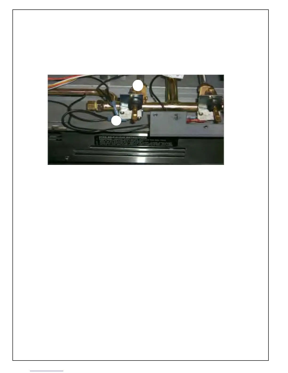
Figure 17-1
A
B
1. Remove top frame
2. Remove Control panel cover
3. Remove knobs
4. Remove 4 screws on either side of control panel to
release bull nose
5. Remove the 3 screws that go through the bezel
into the control panel on each side.
6. Slowly pull control panel forward and lift up to
access valves and swi tches
7. Reach through manif old bracket to release switch
on valve on right side use box end wrench on
valves to remove screws
8. Disconnect gas tube on back before removing
switch from the valve.
9. Break nut loose on front of switch - remove switch
Figure 17-1 shows the microswitch (A) and the valves (B) from the front
of the range after the control panel cover has been removed.