4-66 Inspection, Maintenance and Adjustment K1000896E Operation and Maintenance Manual
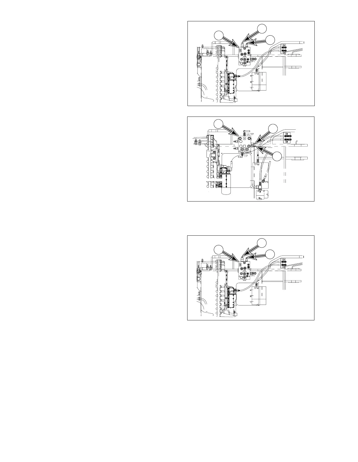
BRAKE CHARGE PRESSURE (S/N 4001 AND
UP)
1. Attach gauge to port (5, Figure 102).
2. Adjust brake charge valve cartridge (2,
Figure 108) on brake and pilot and fan
motor supply valve (1, Figure 108). Relief
pressure for brake charging is 120±5 kg/
cm
2
(1,707 ±70 psi).
CONTROL LEVER ACTIVATION PRESSURE
(S/N 3001 THRU 4000)
1. Attach gauge to port (6, Figure 102).
2. Adjust relief cartridge (3, Figure 109) on
brake and pilot supply valve (1, Figure
109). Relief pressure should be set at
28 kg/cm
2
(398 psi).
3. Loosen lock nut on adjusting screw. Turn
adjusting screw clockwise to raise relief
pressure. Turn adjusting screw
counterclockwise to lower relief pressure.
4. Tighten lock nut after adjustment has been
made.
CONTROL LEVER ACTIVATION PRESSURE
(S/N 4001 AND UP)
1. Attach gauge to port (6, Figure 102).
2. Adjust relief cartridge (3, Figure 110) on
brake and pilot and fan motor supply valve
(1, Figure 110). Relief pressure should be
set at 28 kg/cm
2
(398 psi).
3. Loosen lock nut on adjusting screw. Turn
adjusting screw clockwise to raise relief
pressure. Turn adjusting screw
counterclockwise to lower relief pressure.
4. Tighten lock nut after adjustment has been
made.
1
AOO0190L
2
3
Figure 108
1
2
3
AOO0180L
Figure 109
+3
-2
+43
-30
1
AOO0190L
2
3
Figure 110
+3
-2
+43
-30