10
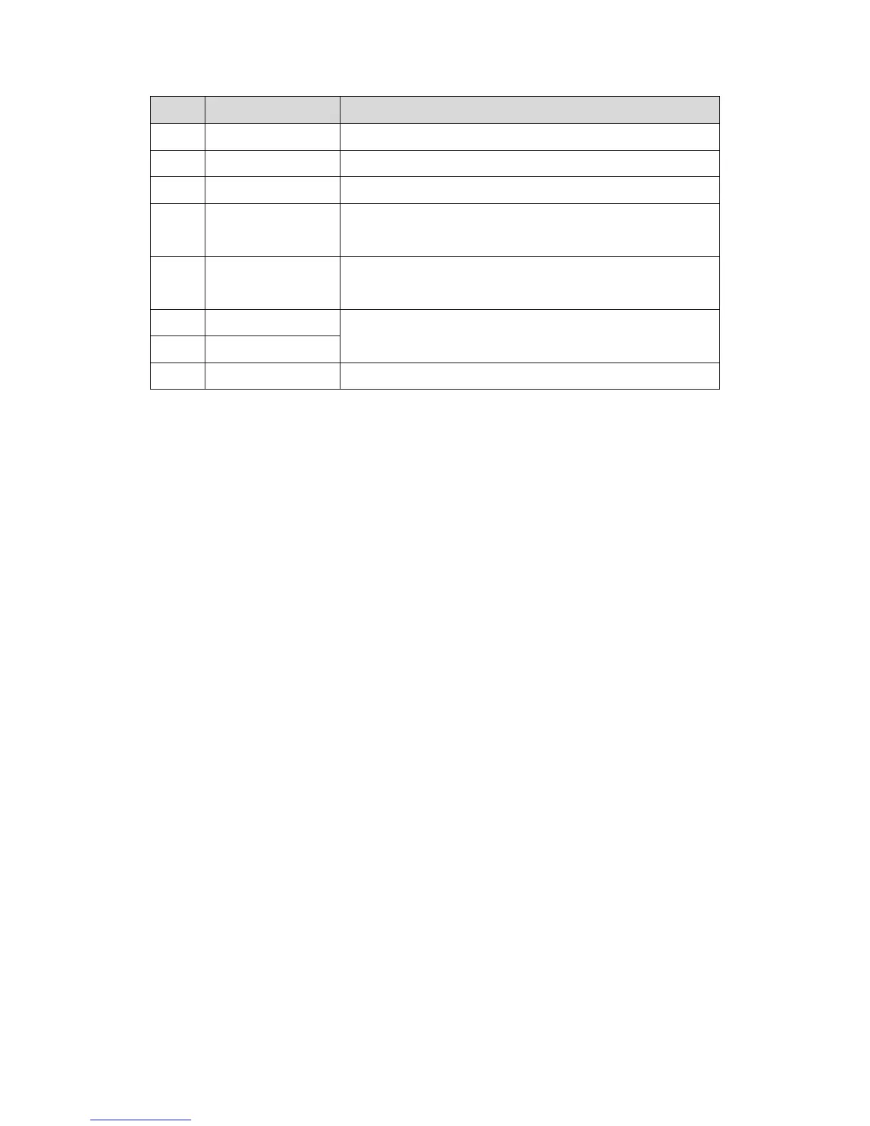
No. Component Name Description
4 USB Device debugging.
5 Power Input DC 12V power input
6 Analog Signal Analog signal connect to distributor
7 Lock Connect to unlock button and door sensor, control NO/NC
lock ON/OFF, see device rear label for details.
8 Wiegand Port Connect to wiegand device,
details.
9 Alarm Out Include 2-ch alarm output and 2-ch alarm input, see device
rear label for details.
10 Alarm In
11 RS485 Connect to RS485 device, see device rear label for details.
Chart 2-2
 Loading...