User’s Manual
23
4 DB25 port
Connects to the audio splitter taken from the package to convert to
audio input port which receives the audio signal from devices such
as microphone. It corresponds to video input ports 2–16.
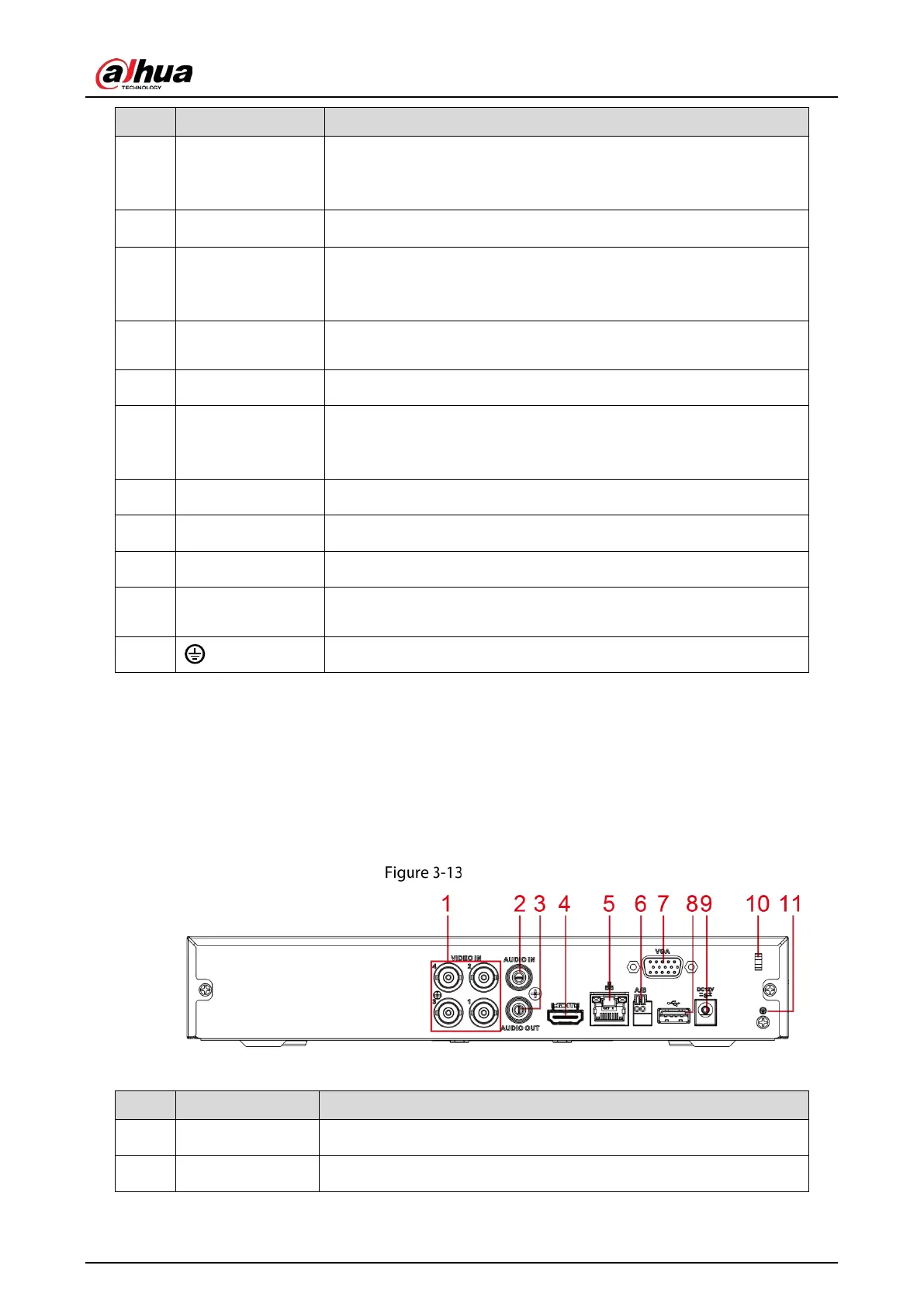
5 Audio output port Outputs audio signal to the devices such as the sound box.
6 HDMI port
High definition audio and video signal output port.
The port outputs the uncompressed high definition video and multi-
channel audio data to the connected display with HDMI port.
7 USB port
Connects to external devices such as USB storage device, keyboard
and mouse.
8 Network port Connects to Ethernet port.
9
RS-485
communication
port
Connects to the control devices such as speed dome PTZ. RS-485_A
port is connected by the cable A and RS-485_B is connected to the
cable B.
10 Power input port Inputs 12 VDC power.
11 VGA port Outputs analog video data to the connected display with VGA port.
12 Power button Turns on/off the DVR.
13
Power cable
fastener
Use a cable tie to secure the power cable on the DVR to prevent loss.
14
Ground terminal.
3.2.2 DH-XVR51xxHS-I2/DH-XVR51xxHS-4KL-I2/DH-XVR5104HS-
I3/DH-XVR5108HS-I3/DH-XVR5104HS-4KL-I3/DH-XVR4104HS-I/DH-
XVR4108HS-I/DH-XVR4104C-I/DH-XVR4108C-I/DH-XVR4116HS-I
Rear panel
Table 3-12 Rear panel description
1 Video input port Connects to analog camera to input video signal.
2 Audio input port Receives audio signal output from the devices such as microphone.
 Loading...