User’s Manual
41
Make sure the front-end device has soundly earthed
Improper grounding might result in chip damage.
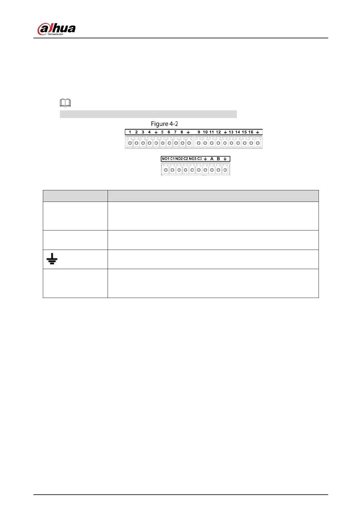
4.3.1 Introducing Alarm Port
The alarm input ports are dependent on the model you purchased.
Alarm ports
Table 4-1 Alarm port description
1, 2, 3, 4, 5, 6, 7, 8, 9,
10, 11, 12, 13, 14, 15,
16
ALARM 1 to ALARM 16. The alarm becomes active in low voltage.
NO1 C1, NO2 C2, NO3
C3
There are four groups of normally open activation output (on/off button).
Ground cable.
485 A/B
485 communication port. They are used to control devices such as decoder.
120 Ω should be parallel connected between A, B lines if there are too many
PTZ decoders.
4.3.2 Alarm Input
Refer to the following figure for more information.
Grounding alarm inputs which includes NO (Normally Open) and NC (Normally Closed) type.
Parallel connect COM end and GND end of the alarm detector (Provide external power to the
alarm detector).
Parallel connect the Ground of the DVR and the ground of the alarm detector.
Connect the NC port of the alarm sensor to the DVR alarm input (ALARM).
Use the same ground with that of DVR if you use external power to the alarm device.
 Loading...