6 | Preparation
Installer reference guide
65
ERGA04~08DAV3(A) + EHBH/X04+08DA*V7
Daikin Altherma 3 R W
4P618958-1 – 2020.03
6.5.4 Overview of electrical connections for external and internal actuators
Item Description Wires Maximum
running current
Outdoor unit and indoor unit power supply
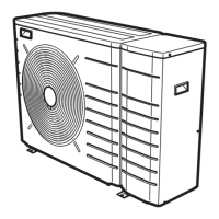
1 Power supply for outdoor
unit
2+GND
(a)
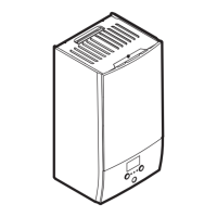
2 Power supply and
interconnection cable to
indoor unit
3
(g)
3 Power supply for backup
heater
See table below. —
4 Preferential kWh rate power
supply (voltage free contact)
2
(e)
5 Normal kWh rate power
supply
2 6.3A
Optional equipment
6 3‑way valve 3 100mA
(b)
7 Power supply for booster
heater and thermal
protection (from indoor
unit)
4+GND
(c)
8 Power supply for booster
heater (to indoor unit)
2+GND 13A
9 Domestic hot water tank
thermistor
2
(d)
10 User interface used as room
thermostat
2
(f)
11 Room thermostat 3 or 4 100mA
(b)
12 Outdoor ambient
temperature sensor
2
(b)
13 Indoor ambient
temperature sensor
2
(b)
14 Heat pump convector 2 100mA
(b)
Field supplied components
15 Shut-off valve 2 100mA
(b)
16 Electricity meter 2 (per meter)
(b)
17 Domestic hot water pump 2
(b)
18 Alarm output 2
(b)
19 Changeover to external heat
source control
2
(b)
20 Space cool/heat operation
control
2
(b)
21 Power consumption digital
inputs
2 (per input signal)
(b)
 Loading...