3 | Components
Service manual
155
EBLA09~16DA + EDLA09~16DA
Daikin Altherma 3 M
ESIE20-06A – 2021.03
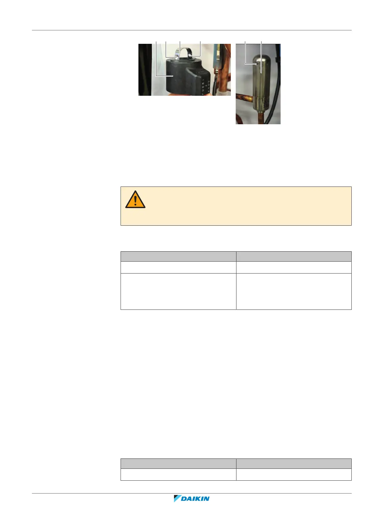
a Expansion valve coil
b Metal bracket
c Nipple
d Notch
e Expanion valve body
2 Route the expansion valve coil harness towards the appropriate PCB.
3 Connect the expansion valve coil connector to the appropriate PCB.
WARNING
When reconnecting a connector to the PCB, make sure to connect it on the correct
location and do NOT apply force, as this may damage the connector or connector
pins of the PCB.
4 Fix the expansion valve coil harness using new tie straps.
5 Install the insulation cap on the expansion valve coil (if applicable).
Is the problem solved? Action
Yes No further actions required.
No Return to "3.9.1Checking
procedures"[4149] of the expansion
valve and continue with the next
procedure.
3.10 Flow switch
3.10.1 Checking procedures
To perform an electrical check of the flow switch
Prerequisite: Stop the unit operation via the user interface.
Prerequisite: Turn OFF the respective circuit breaker.
Prerequisite: Remove the required plate work, see "3.17Plate work"[4230].
1 Turn ON the power of the unit.
2 With the unit powered ON but NOT operating, disconnect the flow switch
connector X45A from the hydro PCB.
3 Measure the voltage on the connector on the hydro PCB.
Result: The measured voltage MUST be approximately 16VDC.
Is measured voltage correct? Then
Yes Continue with the next step.
 Loading...