3 | Components
Service manual
274
EBLA09~16DA + EDLA09~16DA
Daikin Altherma 3 M
ESIE20-06A – 2021.03
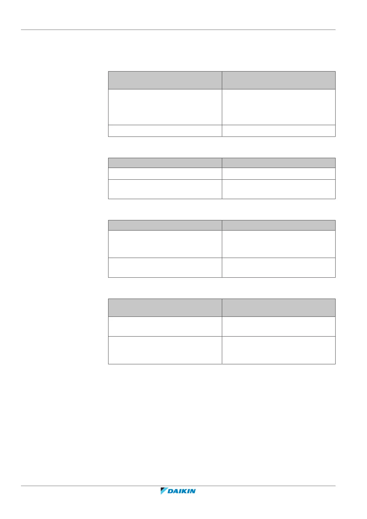
6 With the water pressure sensor connector X7Y connected, measure the
voltage between pin 1–2 (= water pressure output).
7 Check that the measured voltage is in line with the expected voltage through
the measured water pressure.
The measured voltage is inside the
expected range?
Action
Yes Correct the wiring between the hydro
PCB and the water pressure sensor
connector X7Y, see "6.2Wiring
diagram"[4314].
No Continue with the next step.
8 Measure the voltage between pin 2–3 (= water pressure sensor power supply)
of the water pressure sensor connector X7Y.
I measured voltage… Then
Is +5VDC Skip the next step.
Is NOT +5VDC Continue with the next step in the
procedure
9 Unplug the connector X60A and measure the voltage (power supply) between
pin 3–4 on hydro PCB.
Is the measured voltage +5VDC? Action
Yes Correct the wiring between the hydro
PCB and the connector X7Y, see
"6.2Wiring diagram"[4314].
No Perform a check of the hydro PCB, see
"3.12.1Checking procedures"[4160].
10 Disconnect the connector from the water pressure sensor and the connector
X7Y and measure the continuity of the wiring harness.
Is continuity of the wiring harness
correct?
Action
Yes Replace the water pressure sensor, see
"3.23.2Repair procedures"[4274].
No Replace the water pressure sensor
harness, see "3.23.2Repair
procedures"[4274].
3.23.2 Repair procedures
To remove the water pressure sensor wiring harness
Prerequisite: Stop the unit operation via the user interface.
Prerequisite: Turn OFF the respective circuit breaker.
Prerequisite: Remove the required plate work, see "3.17Plate work"[4230].
1 Disconnect the connector from the water pressure sensor.
2 Disconnect the other end of the wiring harness from the connector X7Y.
3 Cut all tie straps that fix the wiring harness, and remove the wiring harness
from the unit.
 Loading...