3 | Components
Service manual
197
EBLA09~16DA + EDLA09~16DA
Daikin Altherma 3 M
ESIE20-06A – 2021.03
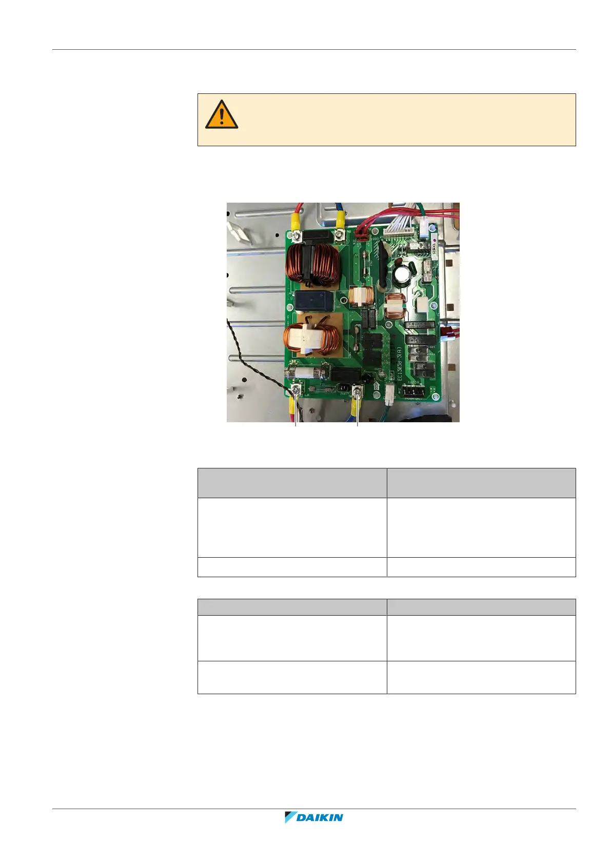
9 Pull the refrigerant pipe forward and slide the main PCB mounting plate
upwards so that the noise filter PCB on the back side is easily accessible.
CAUTION
The noise filter PCB is still connected. Do NOT completely remove the main PCB
mounting plate.
10 Turn ON the power of the unit.
11 Measure the voltage between the wires LA‑NA of the noise filter PCB.
Measured voltage MUST be 230VAC.
a LA
b NA
Is the measured voltage on the PCB
correct?
Action
Yes Return to "Checking
procedures"[4194] procedures of the
PCB and continue with the next
procedure.
No Continue with the next step.
12 Check the power supply to the unit, see "4.1.1Checking procedures"[4284].
Does the unit receive power? Action
Yes Correct the wiring from the main power
supply terminal to the noise filter PCB,
see "Repair procedures"[4200].
No Adjust the power supply to the unit, see
"4.1.2Repair procedures"[4286].
To perform an electrical check of the noise filter PCB
Prerequisite: First check the power supply to the noise filter PCB, see "Checking
procedures"[4194].
1 Measure the voltage between the output wires LB‑NB of the noise filter PCB.
The measured voltage MUST be 230VAC.
 Loading...