Installation manual
134
ERQ100~140A7V1B
Inverter condensing unit
4PW51321-1
Field line connection: Control wiring and cool/heat selection
See figure 10.
Setting the cool/heat operation
1 Performing cool/heat setting with the remote controller
connected to the control box.
Keep the cool/heat selector switch (DS1-1) on the outdoor unit
PC board at the factory setting position IN/D UNIT. (See
figure 11).
2 Performing cool/heat setting with the cool/heat selector.
Connect the cool/heat selector remote controller (optional) to the
A/B/C terminals and set the cool/heat selector switch (DS1-1) on
the outdoor unit PC board to OUT/D UNIT. (See figure 12).
3 Perform cool/heat setting with the field supplied controller.
Set the cool/heat selector switch (DS1-1) on the outdoor unit PC
board (A1P) to OUT/D UNIT. (See figure 12).
Connect the A/B/C terminals with the field supplied controller so
that:
- A/B/C terminals are not connected for cooling operation
- A and C terminals are short-circuited for heating operation
- B and C are short-circuited for fan only operation
■ The wiring from the air handling units must be connected to the
F1/F2 (In-Out) terminals on the PC board in the outdoor unit.
■ After installing the interconnecting wires inside the unit, wrap
them along with the on-site refrigerant pipes using finishing tape,
as shown in figure 13.
For the above wiring, always use vinyl cords with 0.75 to 1.25 mm
2
sheath or cables (2-core wires). (3-core wire cables are allowable for
the cooler/heater changeover remote controller only.)
Precautions when laying power wiring
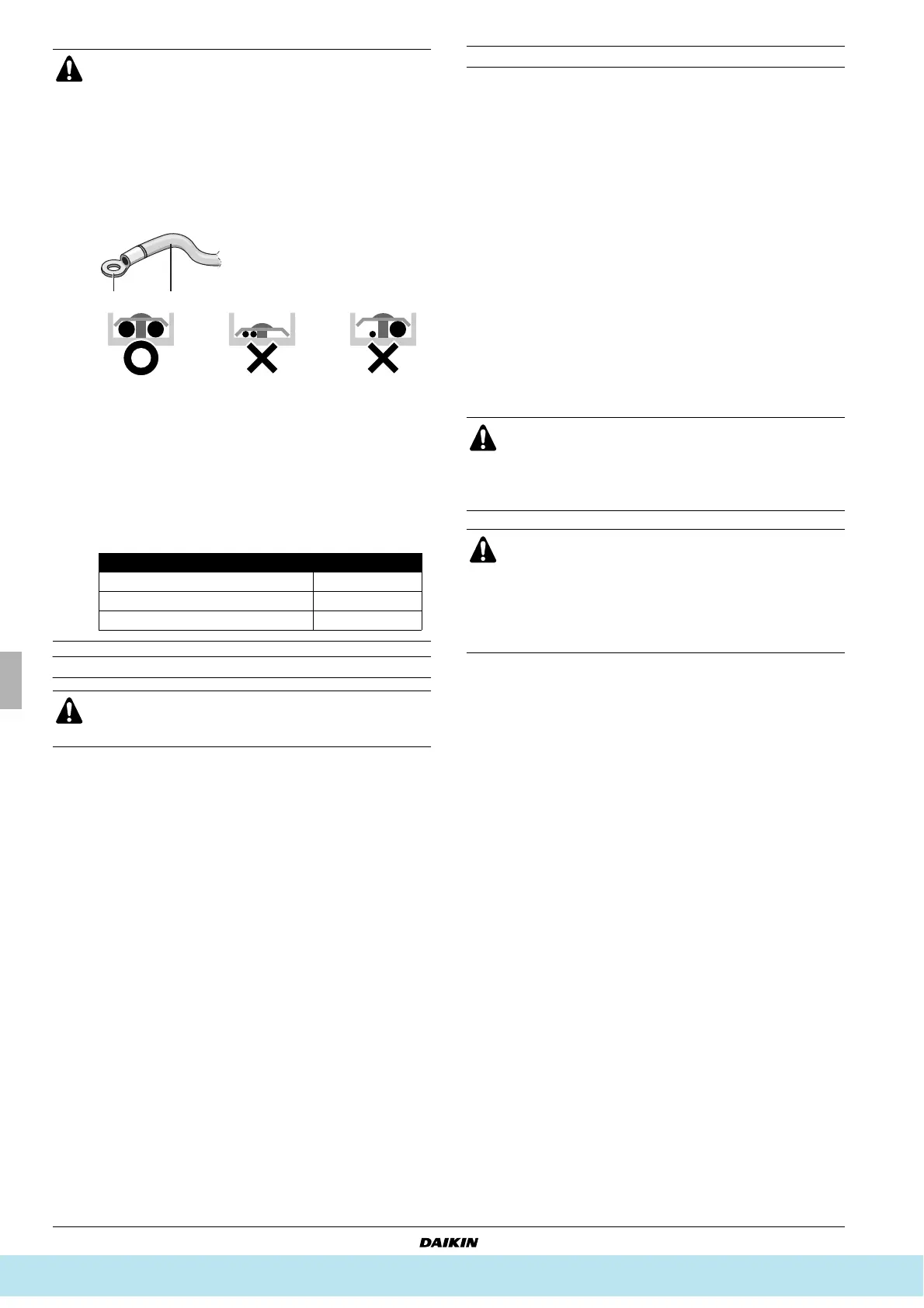
Use round pressure terminals for connections to the power
terminal block.
When none are available, follow the instructions below.
■ Do not connect wiring of different thicknesses to the
power terminal block. (Slack in the power wiring may
cause abnormal heat.)
■ When connecting wiring which is the same thickness,
do as shown in the figure below.
■ For wiring, use the designated power wire and
connect firmly, then secure to prevent outside
pressure being exerted on the terminal board.
■ Use an appropriate screwdriver for tightening the
terminal screws. A screwdriver with a small head will
strip the head and make proper tightening impossible.
■ Over-tightening the terminal screws may break them.
■ See the table below for tightening torque for the
terminal screws.
If an excessive force is applied while connecting a cable to
the terminal block on the PC board, the PC board may be
damaged.
1 Cool/heat selector
2 Outdoor unit PC board
3 Take care of the polarity
4 Use the conductor of sheathed wire (2 wire) (no polarity)
5 Terminal board (field supply)
1 Round pressure terminal
2 Power wire
Tightening torque (N•m)
M5 (Power terminal block/ground wire) 2.39~2.92
M4 (Shielded ground) 1.18~1.44
M3.5 (Control wiring block) 0.79~0.97
1 Cool/heat selector
For low-noise operation or demand operation, it is
necessary to get the optional ’External control adaptor for
outdoor unit’ (DTA104A61/62).
For details, see the installation manual attached to the
adaptor.
■ Be sure to follow the limits below. If the unit-to-unit
cables are beyond these limits, it may result in
malfunction of transmission.
Maximum wiring length: F1/F2=100 m
■ Never connect the power supply to unit-to-unit cabling
terminal block. Otherwise the entire system may
break down.
1 Liquid pipe
2 Gas pipe
3 Interconnecting wiring
4 Insulator
5 Finishing tape
Все каталоги и инструкции здесь: http://splitoff.ru/tehn-doc.html