Installation manual
136
ERQ100~140A7V1B
Inverter condensing unit
4PW51321-1
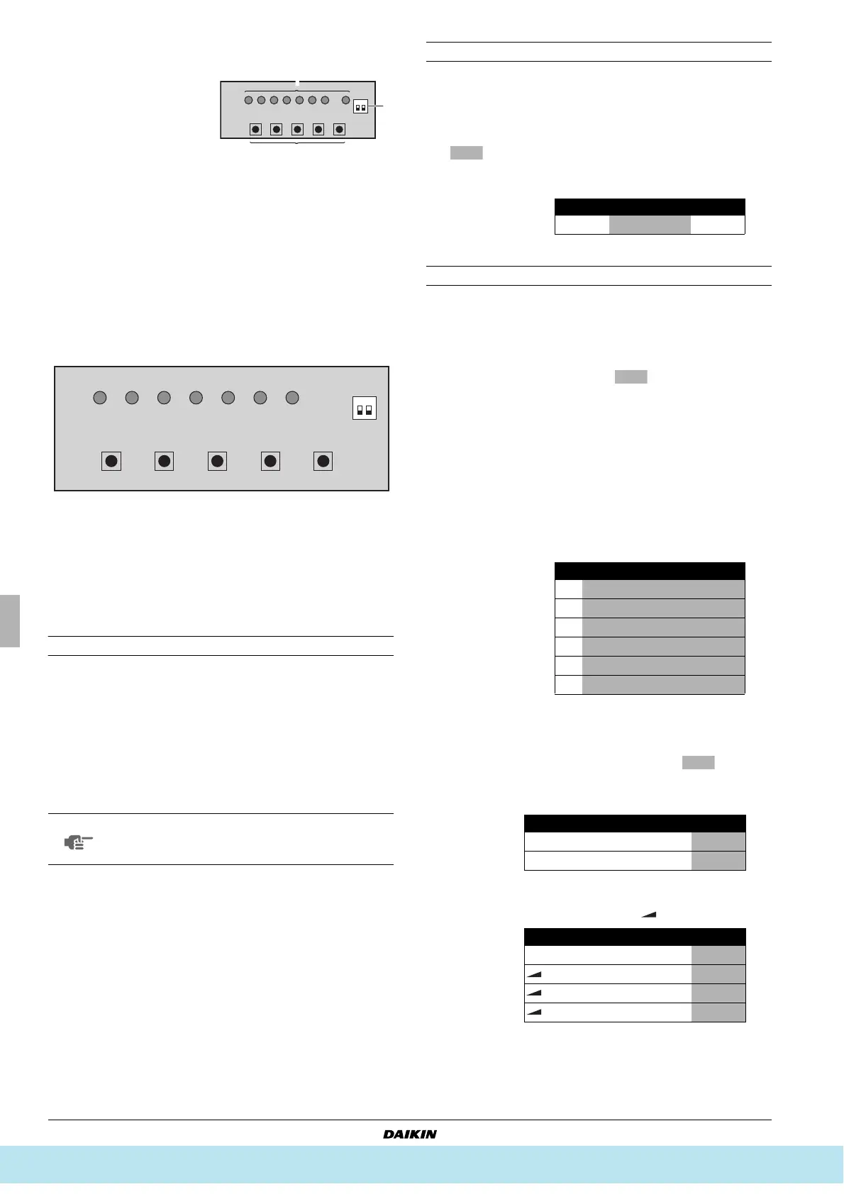
Location of the DIP switches, leds and buttons
Led state
Throughout the manual the state of the leds is indicated as follows:
Setting the push button switch (BS1~5)
Function of the push button switch which is located on the outdoor
unit PCB:
The figure shows state of the led indications when the unit is shipped
from the factory.
Setting the mode
The set mode can be changed with the button according
to the following procedure:
■ For setting mode 1: Press the button once, the
H1P led is off x.
■ For setting mode 2: Press the button for
5 seconds, the H1P led is on w.
If the H1P led is blinking c and the button is pushed
once, it will change to setting mode 1.
Setting mode 1
The H1P led is off (COOL/HEAT selection setting).
Setting procedure
1 Push the button and adjust the led indication to either
one of the possible settings as shown below in the field marked
:
2 Push the button and the setting is defined.
Setting mode 2
The H1P led is on.
Setting procedure
1 Push the button according to the required function
(A~F). The led indication that matches the required function is
shown below in the field marked :
2 When the button is pushed, it indicates the current
setting.
3 Push the button according to the required setting
possibility as shown below in the field marked .
3.1 Possible settings for function A, B and F are (ON) or
(OFF).
3.2 Possible settings for function C
The noise of level 3< level 2< level 1 ( ).
1
Led H1P~H8P
2
Push button switches BS1~BS5
3
DIP switches 2 (DS1-1, DS1-2)
x
OFF
w
ON
c
blinking
For changing the set mode
For field setting
For field setting
For test operation
For resetting the address when the wiring is changed or when
an additional air handling unit is installed
NOTE
If you get confused in the middle of the setting
process, push the button. Then it returns
to setting mode 1 (H1P led is off).
BS1
BS2
BS3
BS4
BS5
MODE
DS1 1 2
ON OFF
TEST/
HWL
IND MASTER SLAVE L.N.O.P. DEMAND
H1P H2P H3P H4P H5P H6P H7P
MODE SET RETURN TEST RESET
BS1 MODE
BS1 MODE
BS1 MODE
BS1 MODE
BS1 MODE
1 In case of COOL/HEAT setting by each individual outdoor unit
circuit.
H1P H2P H3P H4P H5P H6P H7P
1
xxc x xxx
Possible functions
A additional refrigerant charging operation (not applicable).
B refrigerant recovery operation/vacuuming operation.
C automatic low noise operation setting at nighttime.
D low noise operation level setting ( ) via the external
control adapter.
E power consumption limitation setting ( ) via the external
control adapter.
F enabling function of the low noise operation level setting
( ) and/or power consumption limitation setting
( ) via the external control adapter (DTA104A61/62).
H1P H2P H3P H4P H5P H6P H7P
A
w x w x w x x
B
w x w x w x w
C
w x w x w w x
D
w x w w x x w
E
w x w w w w x
F
w x x w w x x
H1P H2P H3P H4P H5P H6P H7P
ON
wxxxxc x
OFF
(*)
(*) This setting = factory setting.
wxxxxx c
H1P H2P H3P H4P H5P H6P H7P
OFF
(*)
(*) This setting = factory setting.
wxxxxx x
wxxxxx c
wxxxxc x
wxxxxc c
BS2 SET
L.N.O.P
1
Все каталоги и инструкции здесь: http://splitoff.ru/tehn-doc.html