EKEQFCBV3 + EKEQDCBV3
Option kit for combination of Daikin condensing units
with field supplied air handling units
4PW52446-1
Installation and operation manual
61
VALVE KIT INSTALLATION
Mechanical installation
1 Remove the valve kit box cover by unscrewing 4x M5.
2 Drill 4 holes on correct position (measurements as indicated in
figure below) and fix the valve kit box securely with 4 screws
through the provided holes Ø9 mm.
Brazing work
For details, see manual of the outdoor unit.
3 Prepare the inlet/outlet field piping just in front of the connection
(do not braze yet).
4 Remove the pipe fixing clamp (C) by unscrewing 2x M5.
5 Remove the upper and lower pipe insulations.
6 Braze the field piping.
7 After brazing, put the lower pipe insulation back in place and
close it with the upper insulation cover (after pealing off the
liner).
8 Secure the pipe fixing clamp (C) in place again (2x M5).
9 Make sure that field pipes are fully insulated.
Field pipe insulation must reach up to the insulation you have
put back in place as per procedure step 7. Make sure that there
is no gap between both ends in order to avoid condensation
dripping (finish the connection with tape eventually).
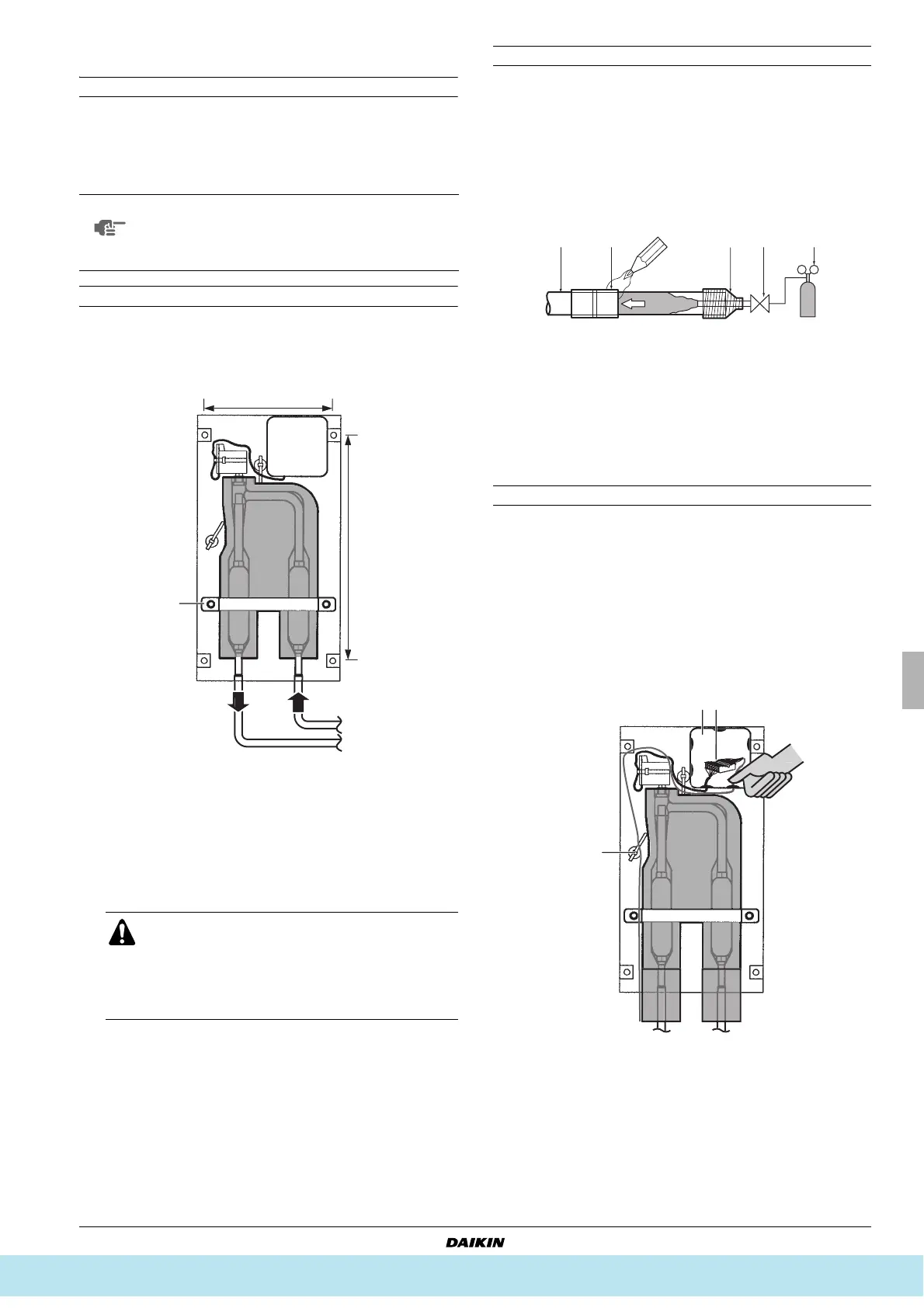
Cautions for brazing
■ Be sure to carry out a nitrogen blow when brazing.
Brazing without carrying out nitrogen replacement or releasing
nitrogen into the piping will create large quantities of oxidized
film on the inside of the pipes, adversely affecting valves and
compressors in the refrigerating system and preventing normal
operation.
■ When brazing while inserting nitrogen into the piping, nitrogen
must be set to 0.02 MPa with a pressure-reducing valve (=just
enough so that it can be felt on the skin).
■ For details, see manual of the outdoor unit.
Electrical work
1 Open the electrical box cover (A).
2 Push out ONLY the second lower wire intake hole (B) from
inside to outside. Do not damage the membrane.
3 Pass valve cable (with wires Y1 ... Y6) from the control box
through that membrane wire intake hole and connect the cable
wires into the terminal connector (C) following instructions as
described in step 4. Route the cable out of the valve kit box
according to figure below and fix with the tie wrap (D). See
"Electric wiring work" on page 62 for more details.
NOTE
■ Make sure that the expansion valve is installed
vertically.
■ Make sure there is enough free space for future
maintenance.
A Inlet coming from the outdoor unit
B Outlet to air handling unit
C Pipe fixing clamp
■ Make sure to cool the filters and valve body with
a wet cloth and make sure the body temperature
does not exceed 120°C during brazing.
■ Make sure that the other parts such as electrical
box, tie wraps and wires are protected from direct
brazing flames during brazing.
1
2.
1 Refrigerant piping
2 Part to be brazed
3 Taping
4 Hands valve
5 Pressure-reducing valve
6 Nitrogen
12 34
6
6
Все каталоги и инструкции здесь: http://splitoff.ru/tehn-doc.html