EKEQFCBV3 + EKEQDCBV3
Option kit for combination of Daikin condensing units
with field supplied air handling units
4PW52446-1
Installation and operation manual
67
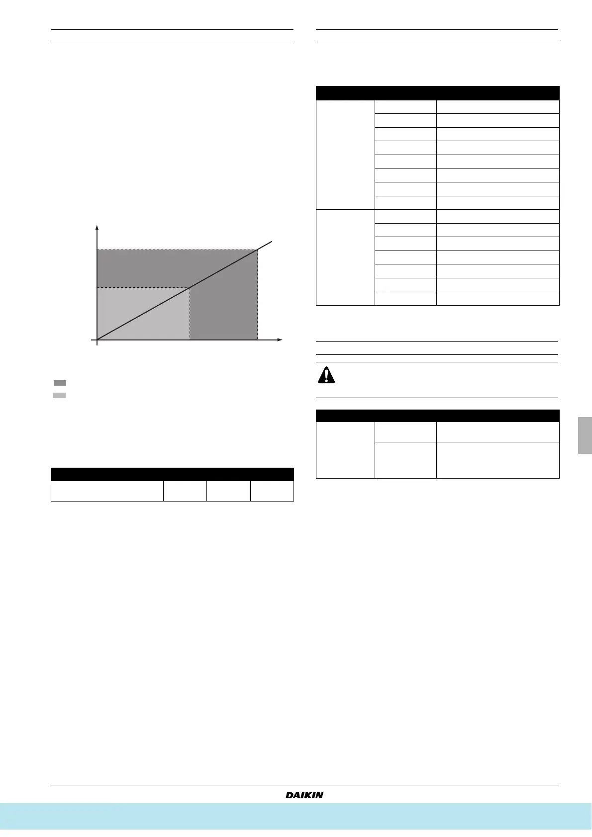
Operation with 0–10 V capacity control
The 0–10 V input is only used for this system of operation and is the
base of the capacity control.
This system needs a field supplied controller with a temperature
sensor. The temperature sensor can be used to control any
temperature:
■ Suction air of the air handling unit
■ Room air
■ Discharge air of the air handling unit
Program the field supplied controller to generate a 0–10 V signal
within conditions as listed. Also refer to the graphic and further data
in this paragraph for more details.
■ When target temperature is reached: 5 V
■ When lower refrigerant temperature is needed: 5–10 V
■ When higher refrigerant temperature is needed: 0–5 V
Operation with fixed T
e
/T
c
temperature control
The evaporating temperature (T
e
)/condensing temperature (T
c
) at
which the application has to operate can be set by code numbers as
listed below.
Operation setting in case of power failure
A Controller voltage output to EKEQFCB
Capacity increase area
Capacity decrease area
Voltage output = linear function with ΔT
ΔT = [actual measured temperature] – [target temperature]
When ΔT=0, the target temperature is reached.
ΔT
max
= maximum temperature variation as defined by installation
Recommended value for ΔT
max
=[1°C~5°C].
ΔT (°C)
–ΔT
max
0
+ΔT
max
Voltage output from controller
(field supply)
0V 5V 10V
0
–ΔT
max
+ΔT
max
ΔT=0
5 10 V
°C
A
Mode No. Code No. Description of setting
(*)
(*) Depending on the operating temperature condition or on selection of the air
handling unit, operation or safety activation of the outdoor unit may take priority
and actual T
e
/T
c
will be different from the set T
e
/T
c
.
13(23)–1
01
T
e
= 3°C
02
T
e
= 4°C
03
T
e
= 5°C
04
T
e
= 6°C (factory setting)
05
T
e
= 7°C
06
T
e
= 8°C
07
T
e
= 9°C
08
T
e
= 10°C
13(23)–2
01
T
c
= 43°C
02
T
c
= 44°C
03
T
c
= 45°C
04
T
c
= 46°C (factory setting)
05
T
c
= 47°C
06
T
c
= 48°C
07
T
c
= 49°C
Measures must be taken to ensure that after power failure,
T1/T2 is according to the setting of your preference.
Neglecting this caution will result in improper operation.
Mode No. Code No. Description of setting
12(22)–5
01
T1/T2 must be open at power
restore.
(*)
(*) After power failure, T1/T2 must be changed to open (no cooling/heating
requested).
02
After power failure, the status of
T1/T2 must remain identical to the
initial T1/T2 status prior to the power
failure.
Все каталоги и инструкции здесь: http://splitoff.ru/tehn-doc.html