Installation and operation manual
74
EKEQMCBV3
Option kit for combination of Daikin condensing units
with field supplied air handling units
4PW52447-1
INSTALLATION
■ For installation of the air handling unit, refer to the air handling
unit installation manual.
■ Never operate the air conditioner with the discharge pipe
thermistor (R3T), suction pipe thermistor (R2T) and pressure
sensors (S1NPH, S1NPL) removed. Such operation may burn
out the compressor.
■ The equipment is not intended for use in a potentially explosive
atmosphere.
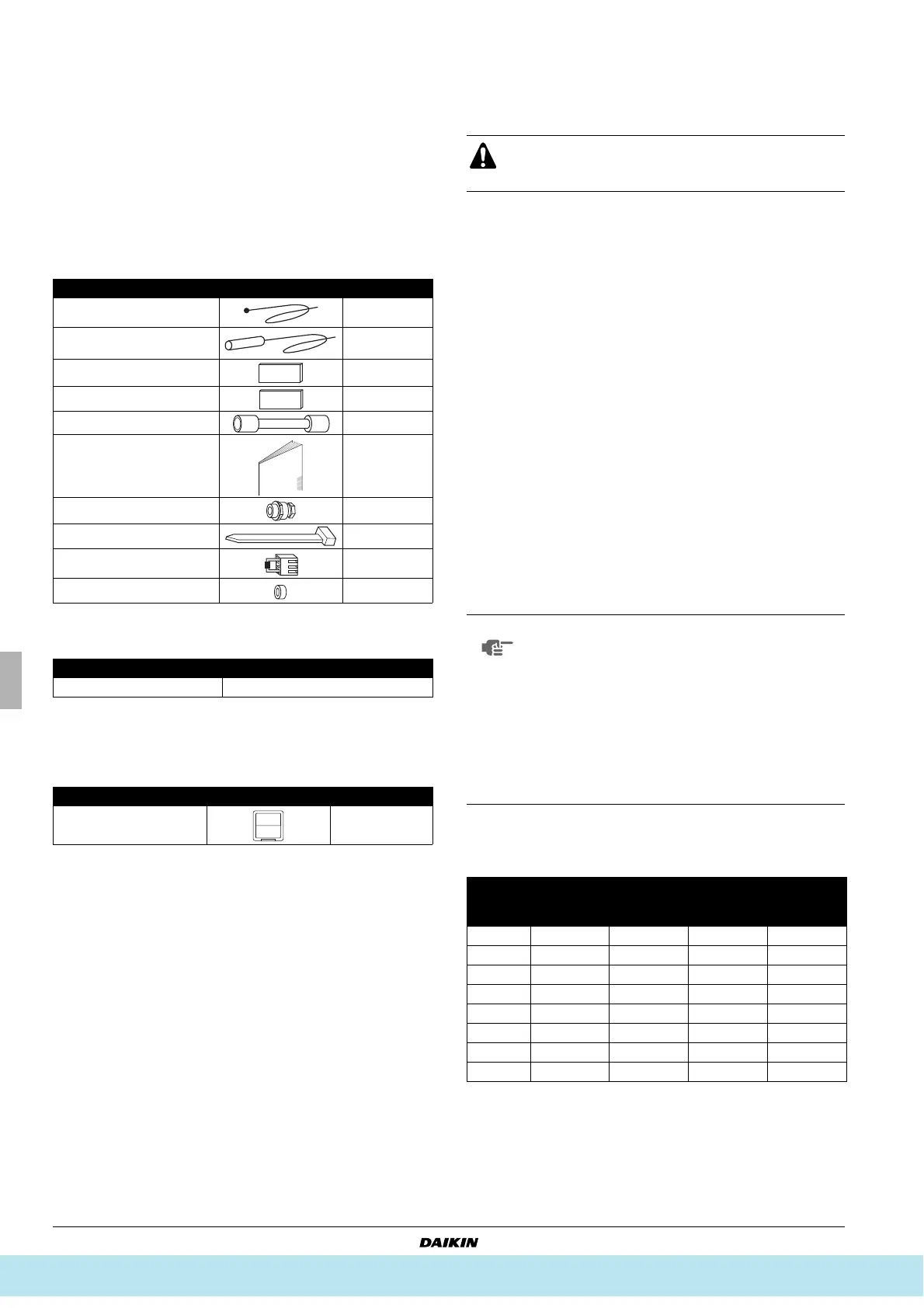
ACCESSORIES
Obligatory accessory
Refer to chapter "Valve kit installation" for installation instructions.
Optional accessories
NAME AND FUNCTION OF PARTS (See figure 1)
BEFORE INSTALLATION
■ Refer to the installation manual of the outdoor unit for details on
refrigerant piping, additional refrigerant charging, and inter-unit
wiring.
■ Precautions for R410A
■ The refrigerant requires strict cautions for keeping the
system clean, dry and tight.
- Clean and dry
Foreign materials (including mineral oils or moisture)
should be prevented from getting mixed into the system.
- Tight
Read "Piping installation" on page 75 carefully and follow
these procedures correctly.
■ Since R410A is a mixed refrigerant, the required additional
refrigerant must be charged in its liquid state. (If the
refrigerant is in state of gas, its composition changes and the
system will not work properly).
■ The connected air handling units must have heat exchangers
designed exclusively for R410A.
Cautions for selection of the air handling unit
Select the air handling unit (field supply) according to the technical
data and limitations mentioned in Table 1.
Lifetime of the outdoor unit, operation range or operation reliability
may be influenced if you neglect these limitations.
This control box can only be used in heat pump applications.
Depending on the heat exchanger, a connectable EKEXV (expansion
valve kit) must be selected to these limitations.
Table 1
Saturated suction temperature (SST) = 6°C, SH (superheat) = 5 K,
air temperature = 27°C DB / 19°C WB.
Quantity
Thermistor (R1T) 1
Thermistor (R3T/R2T)
(2.5 m cable)
2
Insulation sheet 2
Rubber sheet 2
Wire to wire splice 6
Installation and operation
manual
1
Screw nut 9
Tie wrap 6
Capacity setting adaptor 8
Stopper (closing cup) 1
EKEQMCB
Expansion valve kit EKEXV
EKEQMCB
Remote controller 1
Parts and components
1 Outdoor unit
2 Control box
3 Air handling unit (field supply)
4 Field piping (field supply)
5 Expansion valve kit
Wiring connections
6 Outdoor unit power supply
7 Control box wiring
(Power supply and communication between control box and
outdoor unit)
8 Air handling unit thermistors
9 Power supply and control wiring for air handling unit and controller
(power supply is separate from the outdoor unit)
10 Air thermistor control for air handling unit
11 Remote controller
Since design pressure is 4 MPa or 40 bar, pipes of larger
wall thickness may be required. Refer to paragraph
"Selection of piping material" on page 76.
NOTE
■ For maximum number of indoor units, see the
outdoor unit specifications.
■ If the total capacity of the connected indoor units
exceeds the capacity of the outdoor unit, cooling
and heating performance may drop when running
the indoor units.
Refer to the section on performance charac-
teristics in the Engineering Data Book for details.
■ The capacity class of the air handling unit is
determined by the selection of the expansion
valve kit according to Table 1.
EKEXV
class
Allowed heat exchanger
volume (dm
3
)
Allowed heat exchanger
capacity (kW)
Minimum Maximum Minimum Maximum
50 0.76 1.65 5.0 6.2
63 1.66 2.08 6.3 7.8
80 2.09 2.64 7.9 9.9
100 2.65 3.30 10.0 12.3
125 3.31 4.12 12.4 15.4
140 4.13 4.62 15.5 17.6
200 4.63 6.60 17.7 24.6
250 6.61 8.25 24.7 30.8
Все каталоги и инструкции здесь: http://splitoff.ru/tehn-doc.html