SiUS091601EA Outdoor Unit
Part 3 Printed Circuit Board Connector Wiring Diagram 38
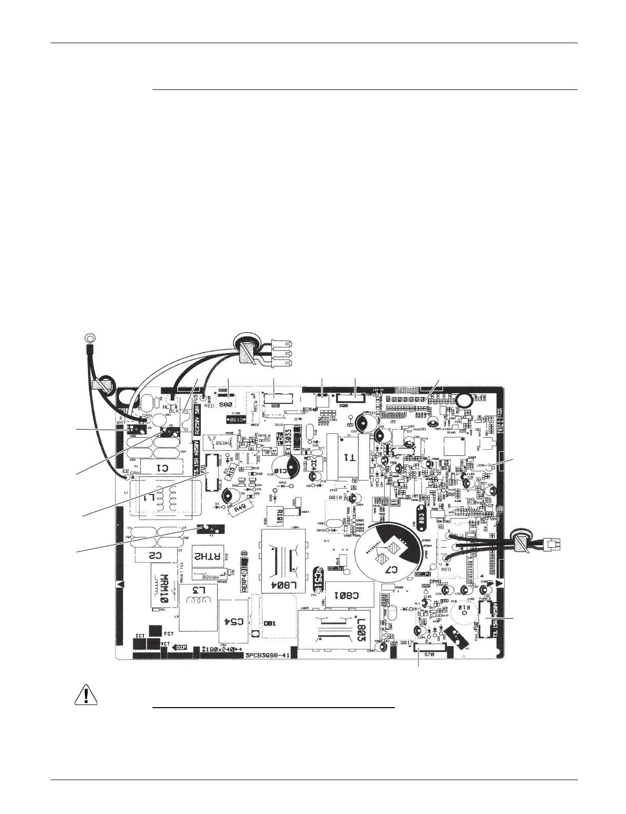
4.3 RXL15QMVJU
Main PCB
Replace the PCB if you cut a jumper unintentionally.
Jumpers are necessary for electronic circuit. Improper operation may occur if you cut any of them.
1) S20 Connector for electronic expansion valve coil
2) S40 Connector for overload protector
3) S70 Connector for DC fan motor
4) S80 Connector for four way valve coil
5) S90 Connector for thermistors
(outdoor temperature, outdoor heat exchanger, discharge pipe)
6) HL1, HN1, S Connector for terminal block
7) E1, E2 Terminal for ground wire
8) U, V, W Connector for compressor
9) FU1, FU2 Fuse (3.15 A, 250 V)
10) FU3 Fuse (30 A, 250 V)
11) J6 Jumper for facility setting
Refer to page 217 for details.
12) LED A LED for service monitor (green)
13) V1, V2, V3 Varistor
U, V, W
FU3
FU1
FU2
V3
V2
V1
S20S80 S40 S90
J6
S70
2P479271-14
E1, E2
HL1, HN1, S
LED A
 Loading...