Removal of PCBs Si041138
18 Removal Procedure
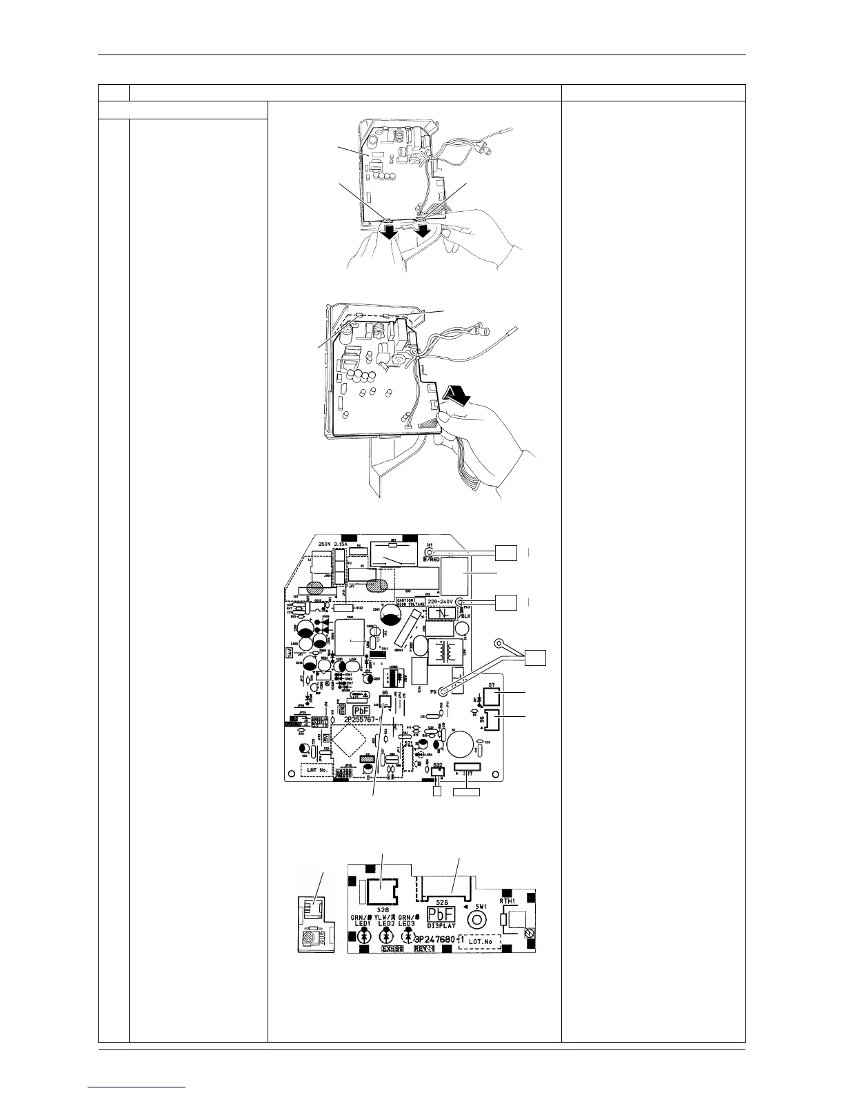
7. Remove the control PCB.
1
Release the 2 lower
hooks.
2
Lift up the bottom of the
control PCB and pull it
out.
When reassembling the
control PCB, make sure that
it is fixed by 2 upper hooks.
3
The figures show the
names of the PCB
component parts.
[S1]: AC fan motor
[S5]: thermal fuse
[S6]: swing motor
[S7]: AC fan motor (Hall IC)
[S27]: display PCB
[S32]: indoor heat exchanger
thermistor
[S26]: control PCB
[S28]: signal receiver PCB
[S29]: display PCB
+
LED3 is not mounted.
Step Procedure Points
Control
PCB
Hook Hook
(R13171)
Hook
Hook
(R13172)
[S7]
[S6]
[S27][S32][S5]
[S1]
(R12699)
[S26]
[S28]
(R12737)
[S29]