FTX-N/U, FVXS-N, FDMQ-R Series EDUS091558E
387
3P363899-2D
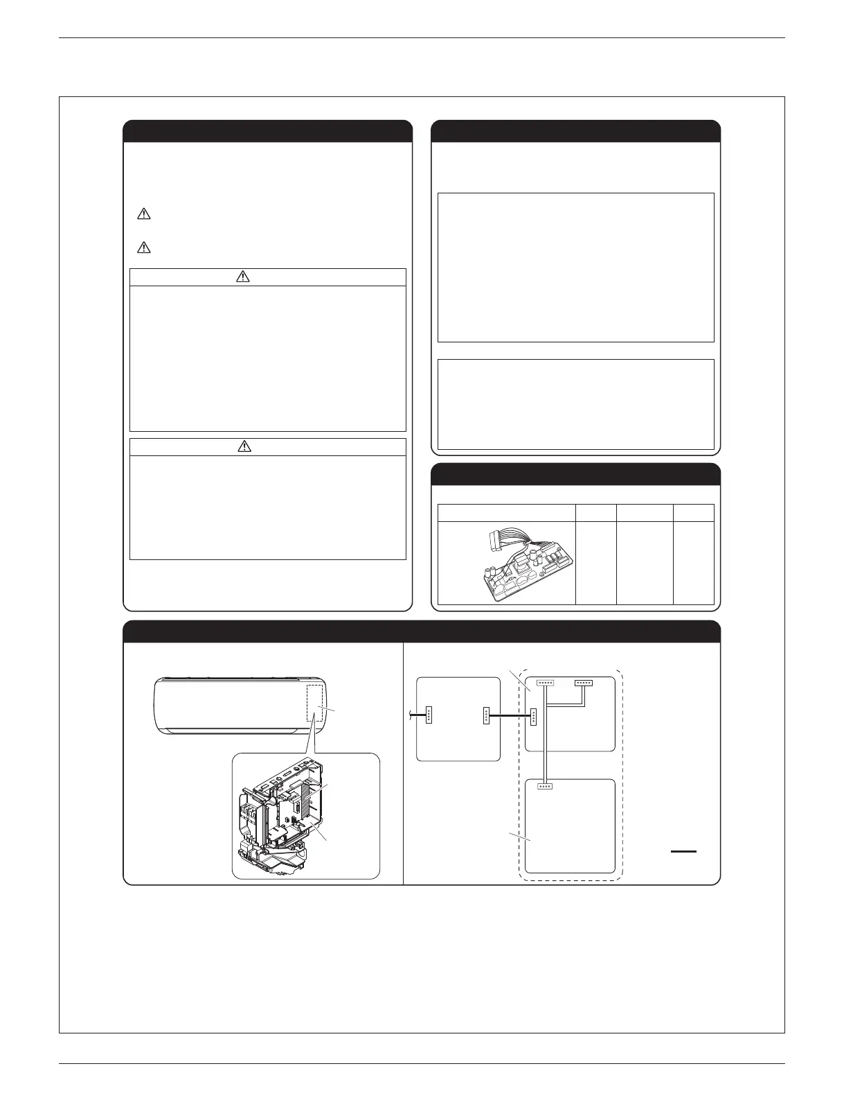
Inside the indoor unit
This set
S602 S601
S403
S21
To central control
device
Option:
KRP413AB1S
KRP928BB2S
PCB of indoor unit
Electrical
wiring box
This set is an interface that connects a central control device to a room
air conditioner and allows you to perform the following operations, or
monitoring, in combination with the central control device using
KRP413AB1S or KRP928BB2S (sold separately).
r
Starting and stopping the air conditioner, and setting the mode and
temperature, through the central control device or the wired remote controller.
(64°F to 90°F (18°C to 32°C) in COOL operation, 57°F to 82°F (14°C to 28°C)
in HEAT operation, none in FAN operation)
r
Monitoring the operating conditions, occurrence of errors, and contents of
errors of the air conditioner through the central control device or the wired
remote controller.
r
Restricting the operation with a wireless remote controller found near the air
conditioner, such as starting and stopping operation, changing the mode, or
setting the temperature, through the use of the central control device, coin
timer, or card key.
r
Zone control through the central control device.
r
Restoring the operating conditions of the air conditioner to the previous
conditions at the time of power recovery in case of power outage.
r
Group control (i.e., the control of multiple indoor units through a single
remote controller)
r
Monitoring of the following items: Indoor temperature and operating
EQPFKVKQPUQHVJGTOQEQORTGUUQTKPFQQTHCPGNGEVTKEJGCVGTCPFJWOKFKƂGT
r
%QPVTQNQHVJGHQNNQYKPIKVGOU(QTEGFVJGTOQ1((ƂNVGTUKIPFKURNC[CPF
TGUGVCKTƃQYFKTGEVKQPCKTƃQYTCVGUGVVKPICPFCKTEQPFKVKQPGTEJCTIG
management
r
Energy-saving command, low-noise command, and demand command
The set does not support the following functions.
6JKUUGVKPENWFGUVJGHQNNQYKPIEQORQPGPVU2NGCUGEQPƂTOVJGO
Component Component
Installation
Manual
Quantity Quantity
Main
component
Installation Position Wiring Outline
r&o not install the air EonFitioner Yhere gas leaMage YoulF
De eZRoseF to oRen ƃaOes
IH the gas leaMs anF DuilFs uR arounF the unit it Oa[ EatEh Ƃre
r TouEh a nearD[ Oetal oDLeEt FoorMnoD aluOiniuO sash
etE to FisEharge statiE eleEtriEit[ HroO [our DoF[ DeHore
touEhing this set
(Static electricity from your body can damage this set.)
r.a[ the EaDle seRaratel[ HroO other RoYer EaDles
(Poor wiring may cause external electrical noise.)
Electrical
wiring box
Installation
position
of the set
Note:
Wires indicated by
thick lines
are not included
with the set.
Installation ProEeFure
r Read these 5afet[ ConsiFerations carefully to ensure correct
installation.
r 6JKUOCPWCNENCUUKƂGUVJGRTGECWVKQPUKPVQWA4NIN) and CAUTION.
Be sure to follow all the precautions below: they are all important for
ensuring safety.
5afet[ ConsiFerations Outline (eatures
CoOponents
WA4NIN) Failure to follow any of WARNING is likely to result
in such grave consequences as death or serious
injury.
CAUTION Failure to follow any of CAUTION may in some
cases result in grave consequences.
WA4NIN)
r Installation shall De left to the authori\eF Fealer or another
traineF professional
IOproper installation Oa[ Eause Yater leaMage eleEtriEal
shoEM Ƃre or eSuipOent FaOage
r$e sure to use the supplieF or eZaEt speEiƂeF installation
parts
Use of other parts Oa[ Eause the unit to EoOe to fall Yater
leaMage eleEtriEal shoEM Ƃre or eSuipOent FaOage
r$e sure to sYitEh off the unit Defore touEhing an[ eleEtriEal
parts
r$e sure to install a grounF fault EirEuit interrupter
(ailure to install a grounF fault EirEuit interrupter Oa[ result
in eleEtriEal shoEM Ƃre or personal inLur[
CAUTION
r After EoOpleting installation test the unit to EheEM for
installation errors )iXe the user aFeSuate instruEtions
EonEerning the use anF Eleaning of the unit aEEorFing to the
Operation /anual
14.8 <KRP980B2> Interface Adaptor for Residential Air Conditioner



 To Next Page