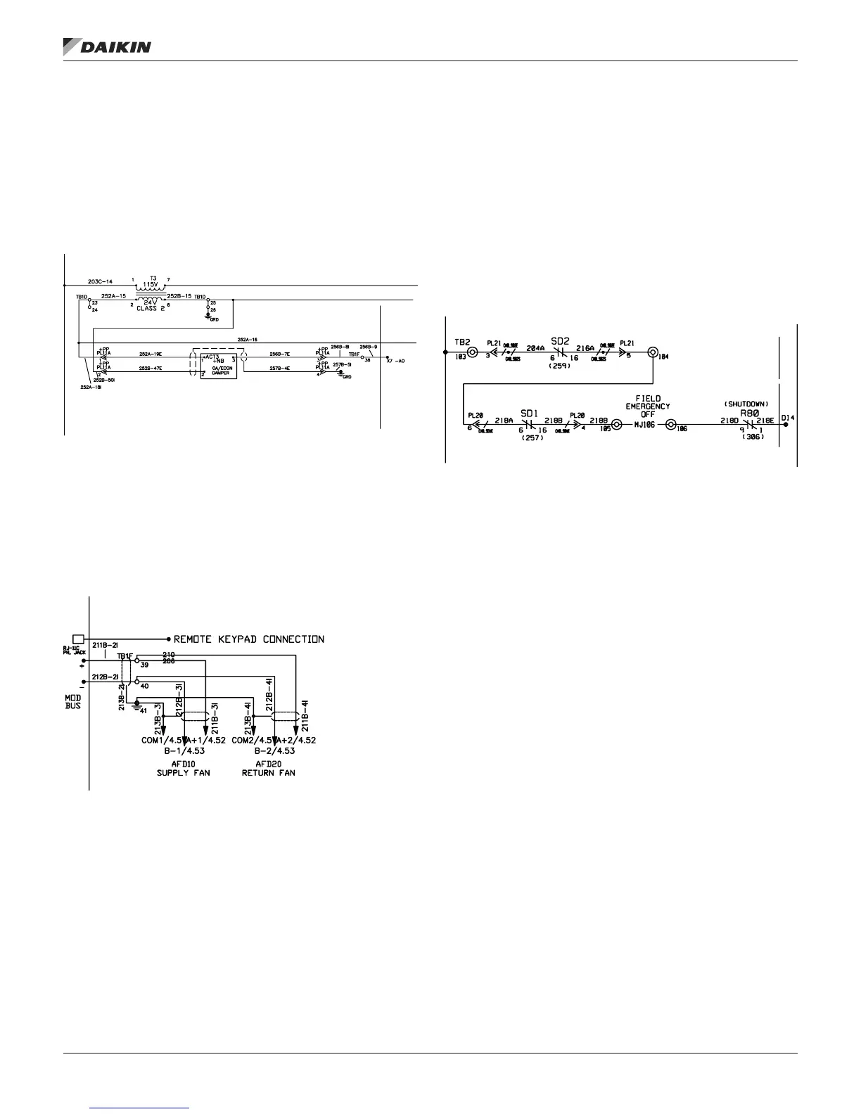
Actuators
The actuators are controlled by an analog signal from the
unit controller. Damper actuators utilize a 0-10VDC analog
signal while modulating heating/cooling valve actuators utilize
a 210VDC signal. Spring-return actuators are used for the
0 - 30% outdoor air and economizer dampers. The mixing
dampers are normally closed to the outside air.
Figure 15: Actuator Wiring Diagram
Variable Frequency Drives (VFD’s)
When controlling discharge, return or exhaust fan, energy
recovery wheel or evaporating condenser fan variable
frequency drives, the MicroTech III controller uses an internal
ModBus communications channel for control and monitoring of
the Variable Frequency Drives.
Figure 16: VFD Wiring Diagram
Smoke Detectors
Field installed smoke detectors in the return air ductwork or
the supply air ductwork can be coordinated with the units
operation through the main controller’s binary input, DI4. This
input is wired to TB2 and the supply air smoke detector can be
wired between terminals 103 and 104 and the return air smoke
detector can be wired between terminals 104 and 105. The T2
transformer supplies 24 V (ac) across each of these terminals
and a dry set of contacts can be wired to these terminals
respectively. This and additional wiring information can be seen
on the input wiring schematics at line number 220.
Figure 17: Smoke Detector Wiring Diagram
NOTE: Factory smoke detectors are wired the same as eld
mounted.
ECM (Electronically Commutated Motor)
fan/motor
The Rebel unit is equipped with a direct drive, ECM
(Electronically Commutated Motor) fan/motor combination
with a built in inverter. When equipped, the exhaust fan will
be the same. The Maverick II unit also has this as an exhaust
fan option. The MTIII controller uses an internal Modbus
communications channel for control and monitoring of the ECM
fan/motor.
desCrIpTIon of operaTIon
www.DaikinApplied.com 13 IM 919-3 • MICROTECH III CONTROLLER