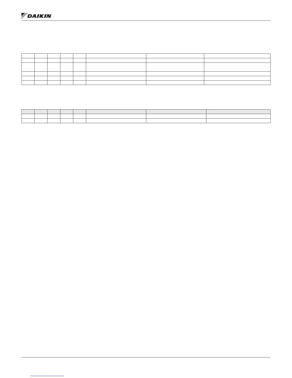
EBTRON or Field OA Flow Station Wiring
MPS (17-50 Tons)/DPS Expansion Module B
X 2 X Reheat #1 0–10 VDC 1 = 2 & 28 = 2
X 3 X Gas Heat LS2 Switch Dry Contact 1 = 0 & 10 = 4
X 3 X OA Flow 0–10 VDC or 4–20 mA
1 = 2, 3 or 4 & 8 = 1, 2, 3, 5, 6 or 7 & 9 = 6
& 30 ≠ 3, 4, 5 or 6
X 4 X FSG Alarm Input (FSG-3) 1=0 & (10=3 or 10=4)
X 4 X Supply Temp Leaving Wheel 10K Thermistor (STD) 1 = 2, 3 or 4 & 20 > 0 & 30 ≠ 3, 4, 5 or 6
X 5 X Exhaust Temp Leaving Wheel 10K Thermistor (STD) 1 = 2, 3 or 4 & 20 > 0 & 30 ≠ 3, 4, 5 or 6
See Table 8 on page 18
RTU/SCU/MPS (62-70 Tons) Expansion Module E
# DI AI DO AO Point Comments Cong. Code Condition
X 1 X OA Flow 0–10 VDC or 4–20 mA 1 = 0 & 8 = 1, 2, 3, 5, 6 or 7 & 9 = 6
X 2
On Maverick (MPS) and Rebel (DPS) units the OA ow station
needs to be wired to terminals X3 and M on expansion module
B. On Rooftop (RTU) and Self Contained (SCU) units, the
OA ow station needs to be wired to terminals X1 and M on
expansion module E. Terminal M is common for all analog
inputs. Make sure the polarity is correct on the eld wiring to
read a valid CFM value. See Table 13 on page 23
IM 919-3 • MICROTECH III CONTROLLER 30 www.DaikinApplied.com
fIeld wIrIng