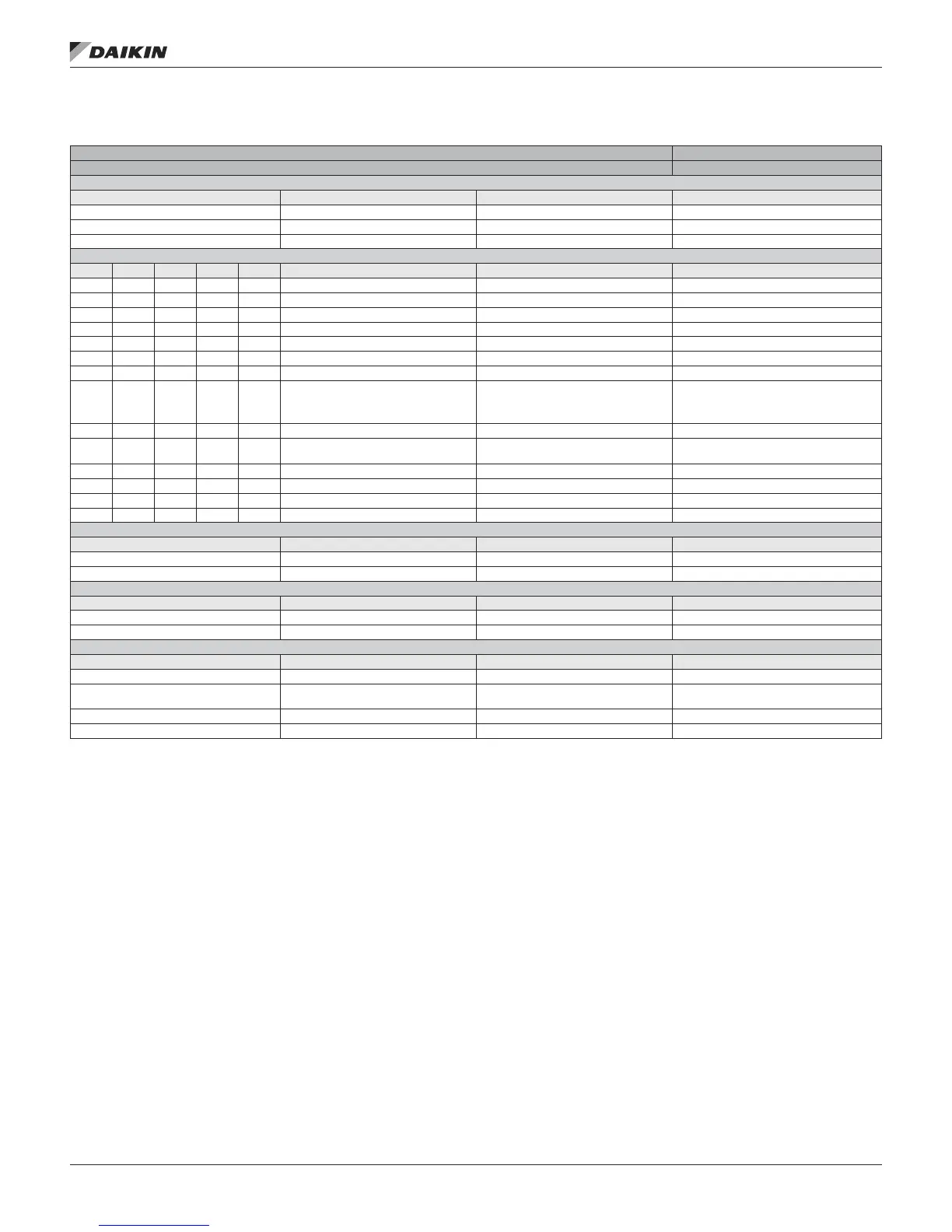
ConTroller InpuTs/ouTpuTs
Table 4: RTU/MPS/DPS/DPH Main Control Board I/O
I/O Cong. Code Condition
PolyCool 600 Main Controller — RTU & MPS & DPS Pos. 1 = 0, 2, 3 or 4
Analog Inputs — NTC
# Point Comments Cong. Code Condition
AI 1 Discharge Temperature 10K Thermistor (STD) All
AI 2 Return Temperature 10K Thermistor (STD) 8 <> 2 or 8 = 2 and 20 > 0
AI 3 Outdoor Temperature 10K Thermistor (STD) All
Universal Inputs/Outputs
# DI AI DO AO Point Comments Cong. Code Condition
X 1 X CO
2
/Min OA/OA CFM 0–10VDC or 4–20 mA 8 = 1, 2 3, 5, 6, 7, 8 or 9
X 2 X Low Pressure 1 and 2
1
1K & 2K Ohm Input 3 = 1 & 4 > 1 & 4 < H
X 2 X Chilled Wtr 2–10 VDC 3 = 2 or 3 = 3
X 2 X Ent Fan & Lvg Coil T 10K Thermistor 1 = 3 or 4 & 19 = 1
X 3 X Space Temperature 10K Thermistor (STD) All
X 4 X Zone Setpoint 5–15 kOhm All
X 4 X DAT Reset 0–10 VDC / 4–20 mA 2 = 1 or 2
X 5 X Enthalpy & Freeze Sw
2
1K & 1.5K Ohm Input
1 = 0 or 2
Enth: 8 = 3, 6, 8 or 9
Frz: 3 = 2, 3 = 3, 10 = 1 or 10 = 5
X 5 X Relative Humidity 0–10 VDC or 4–20 mA 1 = 3 or 4
X 6 X Ent Fan & Lvg Coil T
10K Thermistor (STD) — Gas or
Electric Heat & Dehum
1 = 0 & 19 = 1
X 6 X Duct Static Pressure 4–20 mA 1 = 2, 3 or 4 & 15 = 1–6
X 7 X OA Damper 0–10 VDC RPS 0-10 VDC MPS 8 = 1, 2, 3, 5, 6, 7, 8 or 9
X 8 X Building Static Pressure 4–20 mA 1 = 2, 3, 4 & 16 = 8, 9, A or F
X 8 X OAD End Switch Input Dry Contact 1 = 0 & 8 = 8 or 9
Digital Inputs — Dry Contacts
# Point Comments Cong. Code Condition
DI 1 Air Flow Switch / DHL (R63) Dry Contact All
DI 2 Filter Switch Dry Contact All
Digital Inputs — 24V
# Point Comments Cong. Code Condition
DI 3 Remote START / STOP External 24V All
DI 4 Emergency OFF / DHL (R63) External 24 V All
Digital Inputs — 115V
# Point Comments Cong. Code Condition
DI 5 High Pressure 1 115 VAC Input 3 = 1 & 4 > 1 & 4 < H
DI 5
Standard Comp High Pressure
(HP3 / HP5)
1 = 3 or 4
DI 6 High Pressure 2 115 VAC Input 3 = 1 & 4 > 1 & 4 < H
DI 6 Enthalpy Switch 115 VAC Input 1 = 3 or 4 & 8 = 3, 6, 8 or 9
1. When used for LP1 and LP2, LP1 is considered CLOSED when resistance value is 0–799 or 1250–1800. Otherwise LP1 is considered OPEN. LP2 is considered
CLOSED when the resistance value is 0–1249, otherwise LP2 is considered OPEN.
2. Enthalpy switch is considered CLOSED when resistance value is 0–799 or 1250–1800. Otherwise it is considered OPEN. Freezestat is considered CLOSED when
the resistance value is 0–1249, otherwise it is considered OPEN.
IM 919-3 • MICROTECH III CONTROLLER 14 www.DaikinApplied.com
ConTroller InpuTs/ouTpuTs