Staged Cooling Outputs
Rooftop air handlers can be ordered with factory-installed
evaporator coils and the capability to control up to eight stages
of eld-supplied cooling equipment. The MicroTech III outputs
designated for these applications are DO 1-4 and DO 7,8 on
the MCB and DO 1,2 on Expansion board A. These outputs
are wired to terminal block TB4 in the main control panel for
connection to the eld supplied condensing unit. Refer to the
as-built wiring schematics for the unit
Outdoor Damper
When applicable the Outdoor Damper Output supplies 24
VAC to terminal 119 on the eld terminal block (TB2) when the
output is on. To use this signal, wire the coil of a eld supplied
and installed 24 VAC pilot relay across terminals 119 and 117
on TB2. When this output is on, 24 VAC is supplied from the
T3 control transformer through the output relay to energize the
eld relay. Refer to the as-built wiring diagrams.
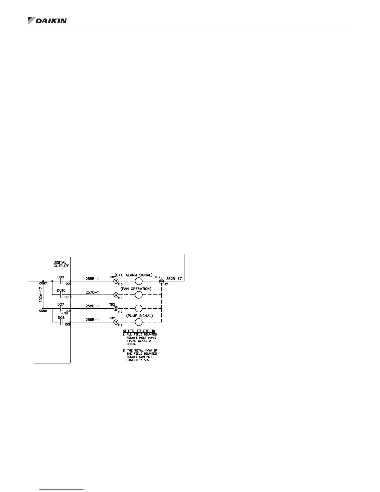
Pump Signal
When applicable the Pump Signal Output supplies 24 VAC to
terminal 113 on the eld terminal block (TB2) when the output
is on. To use this signal, wire the coil of a eld supplied and
installed 24 VAC pilot relay across terminals 113 and 117 on
TB2. When this output is on, 24 VAC is supplied from the T3
control transformer through the output relay to energize the
eld relay. Refer to the as-built wiring diagrams.
Figure 18: Fan Operation Output Wiring Diagram
Field Analog Input Signals
The following inputs may be available for eld connections to a
suitable device.
NOTE: The eld needs to be careful not to ground their
transformer for a eld signal to chassis ground. They
need to use the same ground as the controller to
prevent a voltage potential above 3V. This voltage
potential can damage the Microtech III Controller.
Zone Temperature Sensor Packages
A zone temperature sensor (ZNT1) is optional for all units
except for the 100% outdoor air
Zone Control unit in which case one is required. In all unit
congurations, however, a zone temperature sensor is required
to take advantage of any of the following standard controller
features:
• Unoccupied heating or cooling
• Pre-occupancy purge
• Discharge air reset based on space temperature (DAC
units only)
• Remote timed tenant override
• Remote set point adjustment (CAV-ZTC units only)
A Zone Setpoint Source (Apply Tstat change =No/Yes)
parameter is provided on the keypad/display to allow for
setting the setpoint via the zone thermostat input. The menu is
located in the Heating/Cooling Changeover Setup menu of the
Commission Unit section. When Apply Tstat change is set to
No, the Occupied Cooling Setpoint and the Occupied Heating
Setpoint may be set through the keypad or via a network signal
(all units). In this case these setpoints are changed whenever
the network or keypad value changes.
When Apply Tstat change is set to Yes these setpoints can
only be adjusted through the zone thermostat. This option is
available for all control types (Zone, DAT, and Single zone
VAV). Heating and cooling setpoints must not overlap. The
Occupied Heating Setpoint must be equal to or less than the
Occupied Cooling Setpoint. If a conict occurs from values
entered via the keypad or network, Occupied Heating Setpoint
is automatically adjusted down to eliminate the conict.
When Apply Tstat change =No, the Occupied Heating and
Cooling setpoints may be changed manually by changing the
setpoint displayed on the keypad.
When Apply Tstat change =Yes, the Occupied Cooling Setpoint
is set through a setpoint adjustment included with a wall
mounted space sensor. When the Occupied Cooling Setpoint is
changed by more than 0.5 degrees through the wall mounted
sensor, the Occupied Heating Setpoint is raised or lowered the
same amount so that the difference between the Cooling and
Heating setpoints does not change.
The dead band between the Occupied Cooling Setpoint and
the Occupied Heating Setpoints can be set by setting the Apply
Tstat change to No, setting the differential via the keypad and
resetting the Apply Tstat change back to Yes. The setpoint
adjustment is a resistance value that varies from 5000 ohm to
15000 ohms.
fIeld wIrIng
www.DaikinApplied.com 25 IM 919-3 • MICROTECH III CONTROLLER