CoolIng: MulTIsTage
Compressor Staging
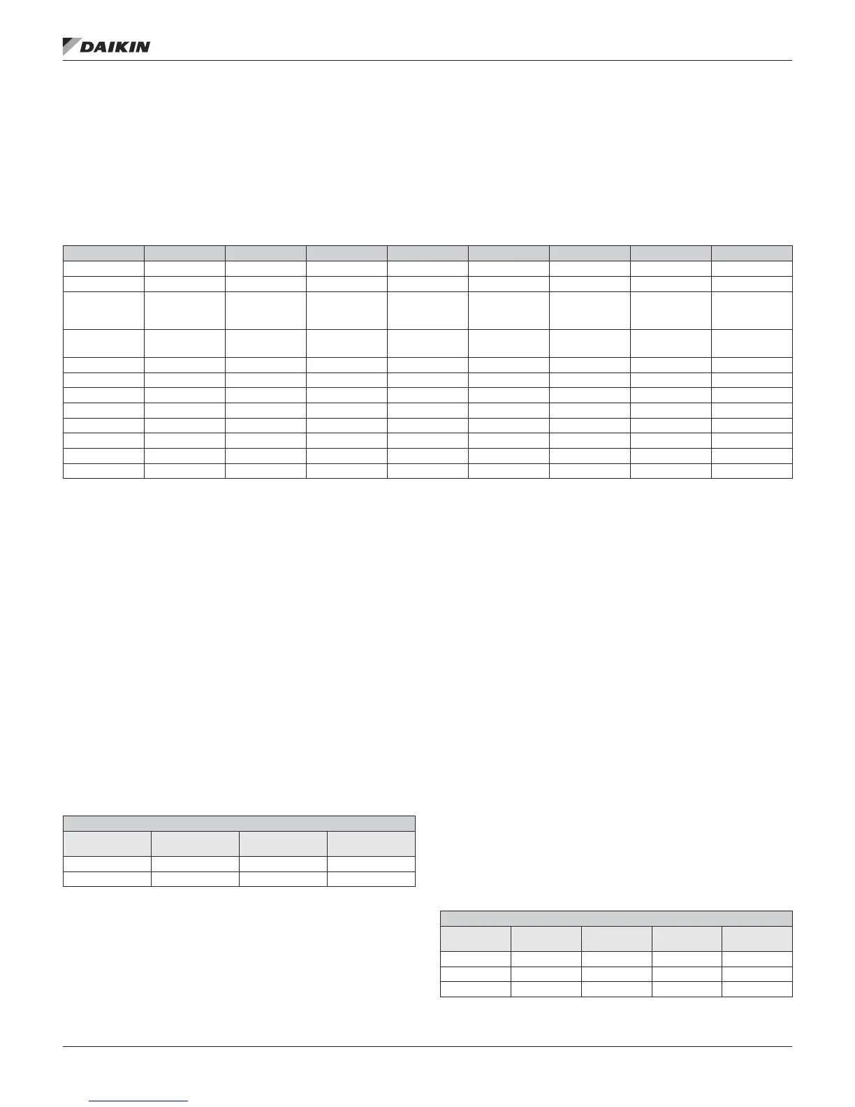
The following table is provided for reference indicating the
compressors that are included in each circuit for all the RTU
and SCU compressor congurations.RTU & SCU Compressor/
Circuit Congurations
Table 14: RTU & SCU Compressor/Circuit Congurations
Comp Cong Circuit #1 Circuit #2 Circuit #3 Circuit #4 Circuit #5 Circuit #6 Circuit #7 Circuit #8
2/2/2 1 2 NA NA NA NA NA NA
2/2/3 1 2 NA NA NA NA NA NA
3/2/4
(RTU R22/R407
& SCU)
1 & 3 2 NA NA NA NA NA NA
3/2/4
(RTU R410A)
1 2 & 4 NA NA NA NA NA NA
3/3/3 1 2 3 NA NA NA NA NA
4/2/4 1 & 3 2 & 4 NA NA NA NA NA NA
4/4/4 1 2 3 4 NA NA NA NA
6/2/6 1, 3 & 5 2, 4 & 6 NA NA NA NA NA NA
6/6/6 1 2 3 4 5 6 NA NA
6/3/6 1 & 3 2 & 4 5 & 6 NA NA NA NA NA
8/4/8 1 & 3 2 & 4 5 & 7 6 & 8 NA NA NA NA
8/8/8 1 2 3 4 5 6 7 8
RTU/SCU-Two Unequal Sized Compressors,
Two Circuits, Three Stages (2/2/3)
With this conguration there is only one xed sequence. If both
circuits are enabled the Maximum Cooling stages is set to 3. If
circuit 2 is disabled the maximum cooling stages is set to 1 and
compressor 1 is staged on and off to maintain the temperature
setpoint. If circuit 1 is disabled the maximum cooling stages is
set to 2 and compressor 2 is staged on and off to maintain the
temperature setpoint.
If a circuit is disabled and then becomes re-enabled, no
change occurs until a new stage up or down request occurs.
At this time the staging is re-aligned to the “normal” condition
for the new stage.
NOTE: During this re-alignment, the cooling stage time
guaranteed on and off times must be observed as
well as a minimum of 10 seconds between starting
more than one compressor.
Table 15: RTU Standard Staging
Compressor Staging
Staging
Sequence
Stage 1
Compressor
Stage 2
Compressors
Stage 3
Compressors
Std-1 1 2 1, 2
StgdClgCap 33% 67% 100%
RPS/SCU-Two Small Comps on Circuit # 1, One
Large Comp on Circuit # 2, Four Stages (RTU
w/3/4/2 R22 or R407C or SCU)
With this conguration there are two xed sequences used
when both circuits are enabled.
If both circuits are enabled, the staging sequence is Std-
1 if compressor # 1 has fewer hours than compressor # 3
and the staging sequence is Std-2 if compressor # 1 does
not have fewer hours than compressor # 3. If Circuit #1 is
disabled compressor # 2 is staged on and off to maintain
the temperature setpoint. If Circuit #2 is disabled the staging
sequence is set to Std-1 if comp #1 has fewer hours than comp
#3 and the staging sequence is set to Std-2 if comp #1 does
not have fewer hours than comp #3. If a circuit is disabled
and then becomes re-enabled, no change occurs until a new
stage up or down request occurs. At this time the staging is
re-aligned to the “normal” condition for the new stage. When
both circuits are enabled the staging sequence is changed only
when the number of stages is zero or Maximum Cooling stages
NOTE: During this re-alignment, the cooling stage time
guaranteed on and off times must be observed as
well as a minimum of 10 seconds between starting
more than one compressor.
Table 16: RPS/SCU Standard Staging
Compressor Staging
Staging
Sequence
Stage 1
Compressor
Stage 2
Compressors
Stage 3
Compressors
Stage 4
Compressors
Std-1 1 1, 3 2, 3 1, 2, 3
Std-2 3 3, 1 1, 2 1, 2, 3
StgdClgCap 25% 50% 75% 100%
CoolIng: MulTIsTage
www.DaikinApplied.com 31 IM 919-3 • MICROTECH III CONTROLLER