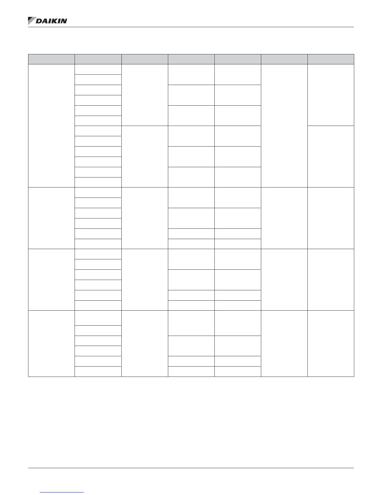
Table 20 continued: Circuit Staging Method
Compressor
Conguration
Lead Circuit/WRV
Control
Circuit Staging
Method
Lead Compressor Lead Circuit
Subsequent
Compressor Staging
Subsequent
Circuit Staging
6/2/6
Lead Circuit=1
No WRV
STD
1, 3 or 5 1
Compressor on
appropriate circuit with
low run hours
Circuit loading
alternates as stage
increases
Lead Circuit =1
WRV
Lead Circuit =2
No WRV
2, 4 or 6 2
Lead Circuit =2
WRV
Lead Circuit =Auto
No WRV
1, 2, 3, 4, 5 or 6 1 or 2*
Lead Circuit =Auto
WRV
Lead Circuit=1
No WRV
ALT
(or dehum. active)
1, 3 or 5 1
Lead circuit is fully
loaded before lag
circuit begins loading
Lead Circuit =1
WRV
Lead Circuit =2
No WRV
2, 4 or 6 2
Lead Circuit =2
WRV
Lead Circuit =Auto
No WRV
1, 2, 3, 4, 5 or 6 1 or 2
Lead Circuit =Auto
WRV
6/3/6
Lead Circuit=1
No WRV
NA
1 or 3 1
Compressor with low
run hours
Circuit with
compressor with low
run hours
Lead Circuit =1
WRV
Lead Circuit =2
No WRV
2 or 4 2
Lead Circuit =2
WRV
Lead Circuit =Auto
No WRV
1, 2, 3, 4, 5 or 6 1, 2 or 3
Lead Circuit =Auto
WRV
1, 2, 3 or 4 1 or 2
8/8/8
Lead Circuit=1
No WRV
NA
1 1
Compressor with low
run hours
Circuit with
compressor with low
run hours
Lead Circuit =1
WRV
Lead Circuit =2
No WRV
2 2
Lead Circuit =2
WRV
Lead Circuit =Auto
No WRV
1, 2, 3 or 4 1, 2, 3 or 4
Lead Circuit =Auto
WRV
1 or 2 1 or 2
8/4/8
Lead Circuit=1
No WRV
NA
1 or 3 1
Compressor with low
run hours
Circuit with
compressor with low
run hours
Lead Circuit =1
WRV
Lead Circuit =2
No WRV
2 or 4 2
Lead Circuit =2
WRV
Lead Circuit =Auto
No WRV
1, 2, 3, 4, 5, 6, 7 or 8 1, 2, 3 or 4
Lead Circuit =Auto
WRV
1, 2, 3 or 4 1 or 2
* When Lead Circuit=Auto and the Circuit Staging Method is STD, the “lead” circuit is re-evaluated based on run hours whenever the number of operating compressors on the circuits is equal.
CoolIng: MulTIsTage
www.DaikinApplied.com 35 IM 919-3 • MICROTECH III CONTROLLER