20 | Electrical installation
Installer and user reference guide
124
RXYSA8~12AMY1B
VRV 5-S system air conditioner
4P752782-1A – 2024.02
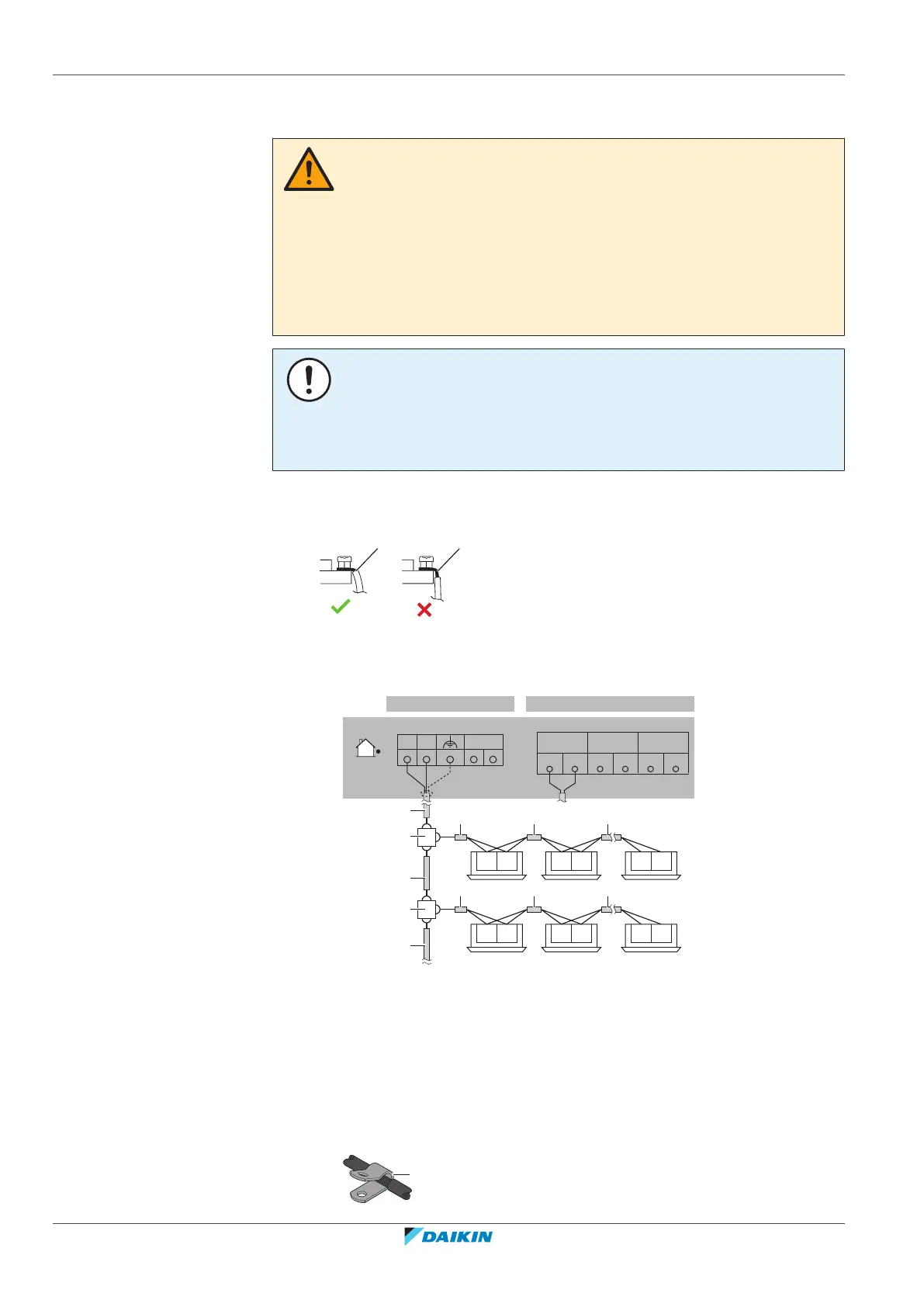
20.2 To connect the electrical wiring to the outdoor unit
CAUTION
▪ When connecting the power supply: connect the earth cable first, before making
the current-carrying connections.
▪ When disconnecting the power supply: disconnect the current-carrying cables
first, before separating the earth connection.
▪ The length of the conductors between the power supply stress relief and the
terminal block itself MUST be as such that the current-carrying wires are
tautened before the earth wire is in case the power supply is pulled loose from
the stress relief.
NOTICE
▪ Follow the wiring diagram (delivered with the unit, located at the inside of the
service cover).
▪ Make sure the electrical wiring does NOT obstruct proper reattachment of the
service cover.
1 Remove the service cover. See "17.2.2To open the outdoor unit"[483].
2 Strip insulation (20mm) from the wires.
a Strip wire end to this point
b An excessive strip length may cause electrical shock or leakage
3 Connect the transmission wiring as follows:
F1 F2 F1 F2 F1 F2
F1 F2 F1 F2 F1 F2
a
a
b
b
8 HP 10+12 HP
X1M (A1P)
F1 F2 SFB
a
a a a
a a
a
X3M
F1 Q2F2F1 Q1F2
TO MULTI
UNIT
TO OUT/DTO IN/D
a Use the conductor of sheathed wire (2wire) (no polarity)
b Terminal board (field supply)
Note: The indoor F1/F2 interconnection cable MUST be shielded:
- 8HP: the shielding is earthed (only at outdoor unit side of the cable) via the
middle screw on the terminal X3M.
- 10+12HP: the shielding is earthed (only at outdoor unit side of the cable) via a
metal P-clamp. Strip the insulation up to the shielding mesh, to provide full
contact of the earth with the shielding. See illustration below: