5 | About the system
Installer and user reference guide
28
RXYSA8~12AMY1B
VRV 5-S system air conditioner
4P752782-1A – 2024.02
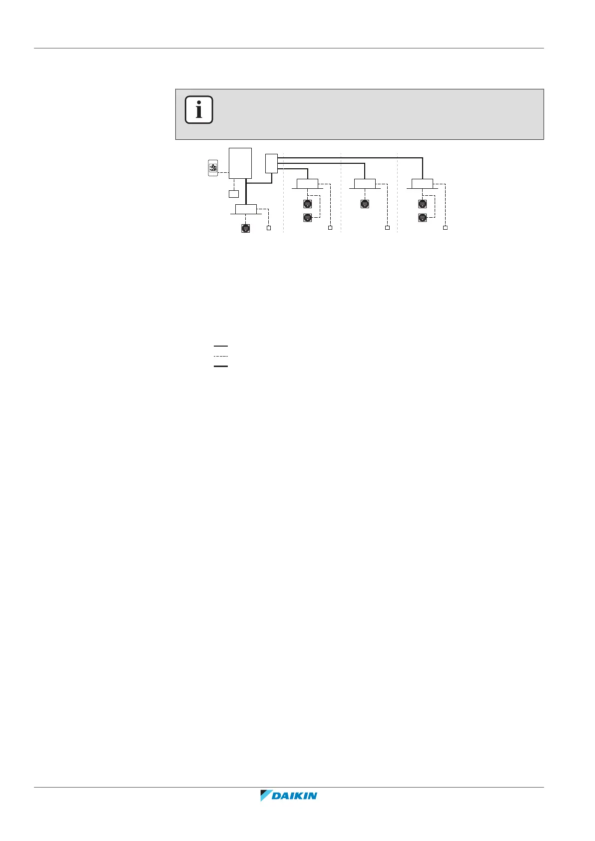
5.1 System layout
INFORMATION
The following figure is an example and may NOT completely match your system
layout
a Heat pump outdoor unit
b Safety valve unit (SV)
c VRV direct expansion (DX) indoor unit
d VRV direct expansion (DX) indoor unit (direct connection from outdoor to indoor)
e Remote controller in normal mode
f Remote controller in alarm only mode
g Remote controller in supervisor mode (mandatory in some situations)
h Centralised controller (optional)
i Option PCB (optional)
j Cool/heat changeover remote control switch (optional)
Refrigerant piping
Interconnection and user interface wiring
Direct connection of indoor units to the outdoor unit
 Loading...


