Page 25 of 58
SK2019 FMCD-V-ECM-001
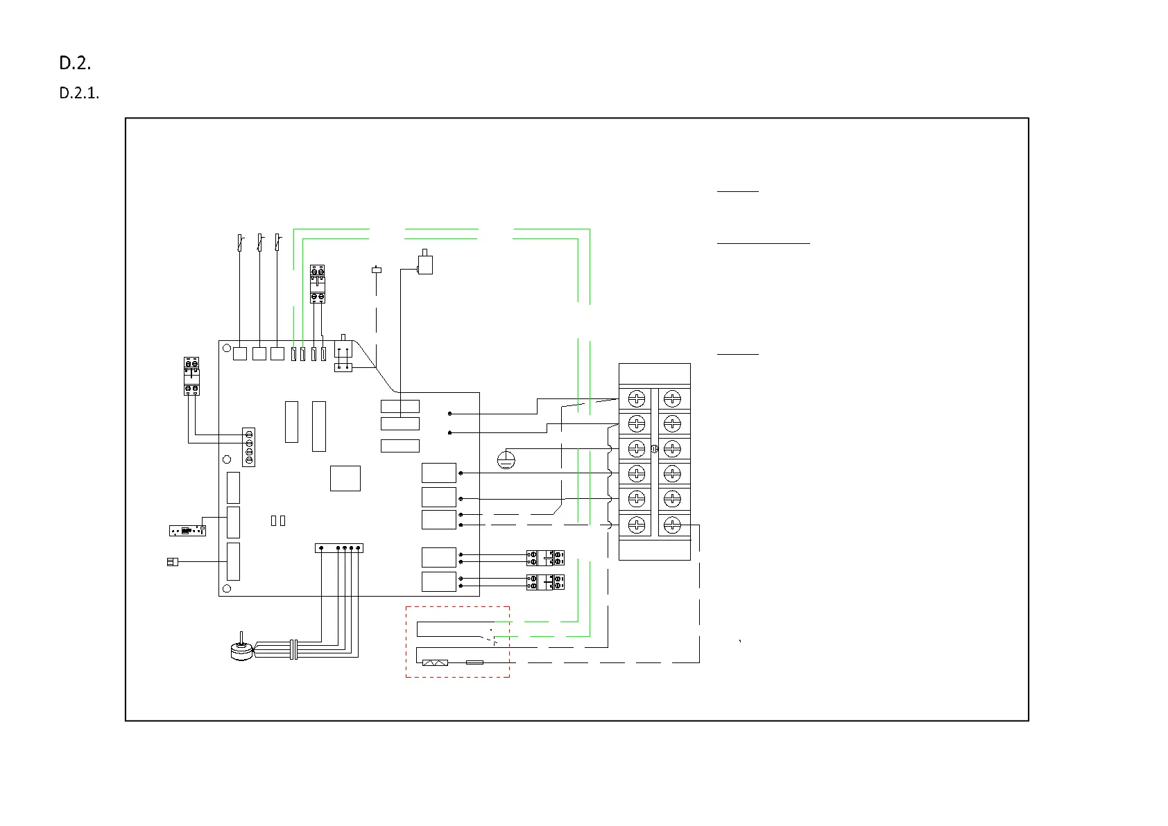
Wiring Diagrams
2-pipe system Total Type Control
Reset switch for SWC-20, 24, 30
Louver Stepping motor
CN1
Dip switch A
N
L
KEY
N
L
V1 V2
VALVE1
HEAT
VALVE2
AUX1
AUX2
FUSE
Dip switch B
Wired Wall
pad plug
A B A B
Yellow/Green
Reset switch SWC06~18
CN4
Plug
Legend:
DIPA-S1
SW1-5: set the unit address
SW6: set unit type: master or slave
Mode Configuration
SW7=0;SW8=0; unit operates in cooling/heating;
SW7=0;SW8=1; unit operates in cooling/heating
with booster EH;
SW7=1;SW8=0 ; unit operates in cooling
SW7=1;SW8=1; unit operates in cooling
with primary EH
DIPB-S2
SW1:Occupancy connect setting
SW2: Unit configuration setting: 0=2pipe system;
1=4-pipe system;
SW3: on/off valve configuration:0= no valve
1=with valve
SW4:preheat setting: 0=36C; 1=28C
SW5,SW6,S3(jump)----RPM selection.
L\N----Power supply
VALVE1:230V on/off valve output;
VALVE2:230V on/off valve output;
HEAT----Electrical heater
AI1:Return air temperature sensor(Tr) ;
AI2:Indoor coil temperature sensor1 (Ti1) ;
AI3:Indoor coil temoeraturesensor 2 (Ti2) ;
AUX1:Voltage free contact; ON:unit in heating mode.
AUX2:Voltage free contact; ON:unit in cooling mode.
ON/OFF:Occupancy contact
CN1 2---Stepping motor
CN3---Serial BUS contacts.
CN4---Ec motor
DIS---Led receiver display
TTL---wired wall pad
CPU
S4 S3
AI3 AI2 AI1
CN2
prog
EH
DIS
TTL1
S1
S2
CN3
ON/OFF
TERMINAL
{
chilled /hot water
4-pipe coil circut sensor
2 pipe sensor (Ti1)
Renturn sensor (Tr)
(Ti2):hot water
EC-S Unit wiring scheme
EH
B A
RS485 plug
A1 A1 A2 A2
Auxiliary heating contact
Auxiliary cooling contact
Electrical heater
FUSE
EC moter
DISPLAY
PROs
PRO contact
110C
IPA19-DL-EC-S