12
Fahrzeug-/Funktionsdecoder ab Firmware-Version 1.11
12
Locomotive/Locomotive function decoder from firmware version 3.12
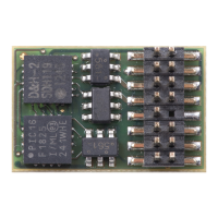
DH21A (2
nd
generation)
21 pin interface
1 22
2 21
3 20
4 19
5 18
6 17
7 16
8 15
9 14
10 13
11 12
GPIO
--
--
AUX4
ZCLK
ZDAT
LR
LV
--
--
Index
G1
G2
GND
M1
M2
--
VS
AUX1
AUX2
AUX3
VCC
M1, M2 .............. Motor connection 1, 2
G1, G2 ............... Track connection 1, 2
LV, LR ................ Front light, rear light (each 150 mA)
AUX1, AUX2 ..... Additional function 1, 2 (each 300 mA)
AUX3, AUX4 ..... Additional function 3, 4
†
)
VS ...................... Supply voltage
ZVS ................... SUSI supply voltage
ZCLK .................. SUSI clock (or AUX5 unamplified) *)
ZDAT ................. SUSI data (or AUX6 unamplified) *)
GND .................. Ground (0 V)
GPIO .................. General input / output (max. +5 V / max. 3 mA)
VCC ................... +5 V / max. 15 mA
*)
Unamplified function outputs: See supplement 3.
†
) The DH21A existists in two different hardware variants:
– Function outputs AUX3, AUX4: each 1,0 A (connecting option -0/-2/-3/-4)
– Function outputs AUX3, AUX4: unamplified *) (connecting option -5)
If necessary: Connect blue wire (common return conductor) to VS.
You can connect a buffer capacitor to ZVS (+) and GND (-).
BA DH engl FW3_12 Druck.indd 12BA DH engl FW3_12 Druck.indd 12 10.05.21 14:2610.05.21 14:26
 Loading...