50 Capacity controller RS8GN202 © Danfoss 11-2013 AK-PC 783
2. Connect LON communication network
The installation of the data communication must comply with
the requirements set out in document RC8AC.
3. Connect supply voltage
Is 24 V, and the supply must not be used by other controllers or
devices. The terminals must not be earthed.
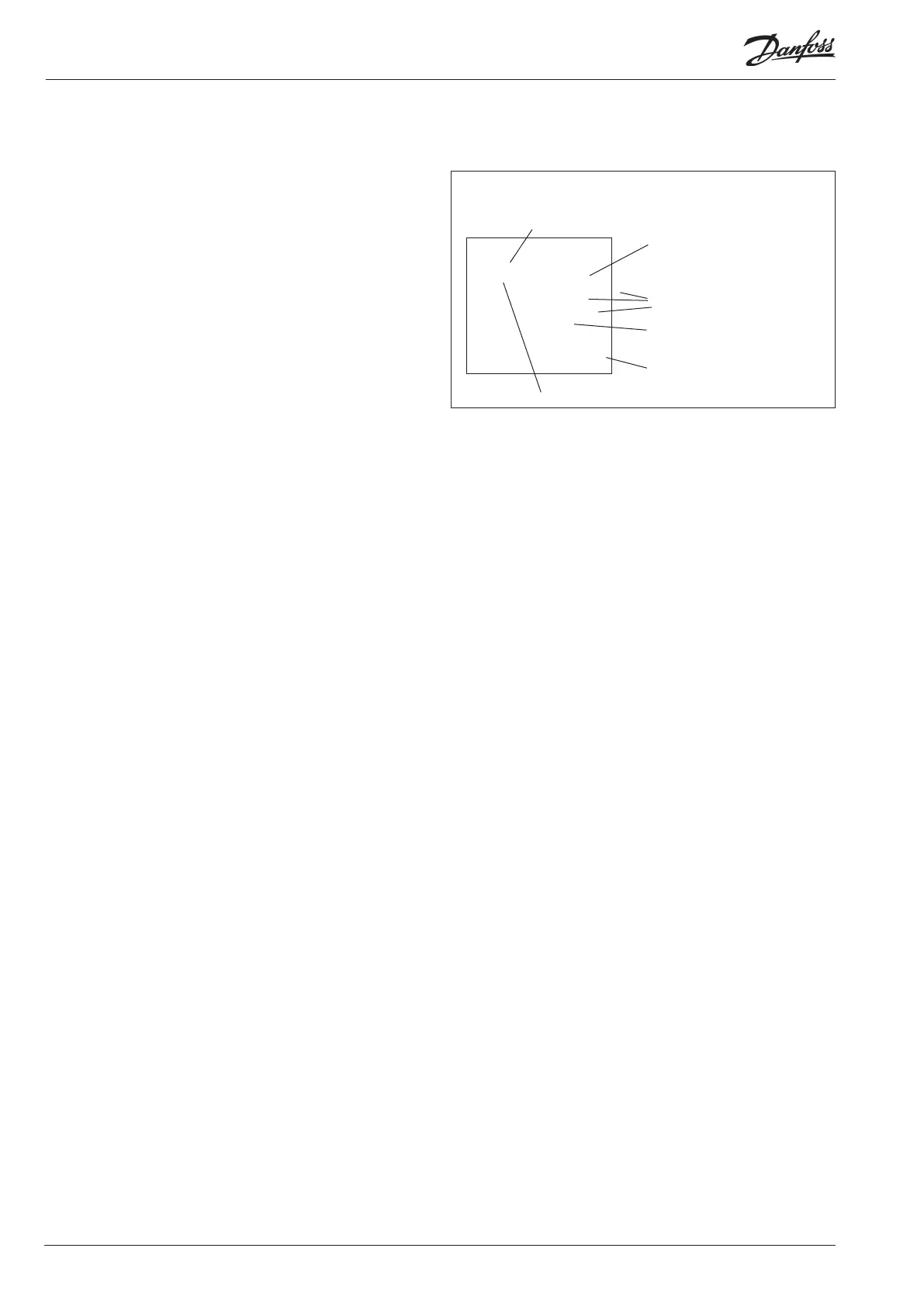
4. Follow light-emitting diodes
When the supply voltage is connected the controller will go
through an internal check. The controller will be ready in just
under one minute when the light-emitting diode ”Status” starts
ashing slowly.
5. When there is a network
Set the address and activate the Service Pin.
6. The controller is now ready to be congured.
■ Power
■ Comm
■ DO1 ■ Status
■ DO2 ■ Service Tool
■ DO3 ■ LON
■ DO4 ■ I/O extension
■ DO5 ■ Alarm
■ DO6
■ DO7
■ DO8 ■ Service Pin
Internal communication
between the modules:
Quick ash = error
Constantly On = error
Status on output 1-8
Slow ash = OK
Quick ash = answer from gateway
in 10 min. after network
installation
Constantly ON = error
Constantly OFF = error
Flash = active alarm/not cancelled
Constant ON = Active alarm/cancelled
External communication
Communication to AK-CM 102
Network installation