100 Capacity controller RS8ER302 © Danfoss 2016-02 AK-CH 650
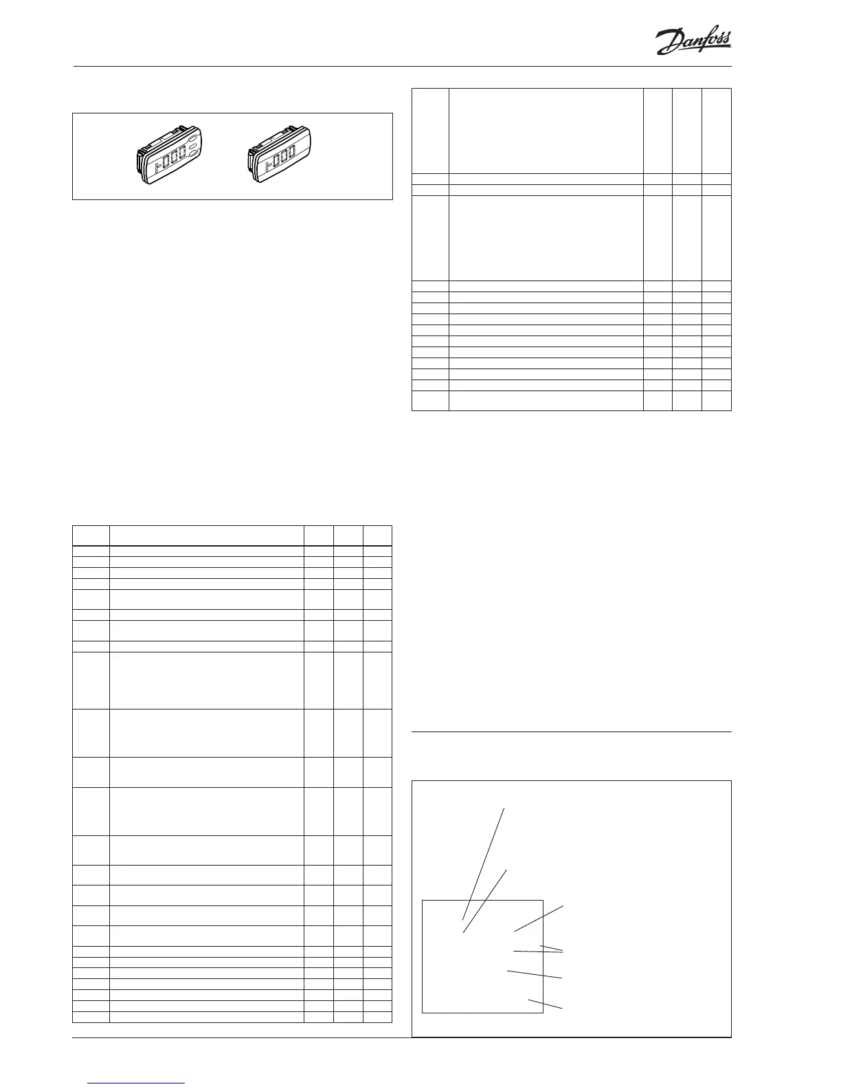
Display of brine temperature and condensing pressure
One to four separate displays can be connected to the controller.
Connection is accomplished by means of wires with plug con-
nections. The display may be placed in a control box front, for
example.
When a display is connected, it will show the value for what is indi-
cated in the conguration:
fx.
- compressors regulation sensor
- P0
- P0 bar (abs)
- S3
- S4
- Ss
- Sd
- Condensors regulation sensor
- Pc
- Pc bar (abs)
- S7
When a display with control buttons is chosen, a simple operation
via a menu system can be performed in addition to the display of
brine temperature and condensing pressure.
No. Function Cond. Suc-
tion
Pack
d02 Defrost stop temperature x x x
o30 Refrigerant setting x x x
d04 Max defrost time (safety time at stop on temperature) x x x
d06 Drip delay. Time before cooling starts after defrost x x x
o57 Capacity setting for condenser
0: MAN, 1: OFF, 2: AUTO
x x
058 Manual setting of condenser capacity x x
o59 Capacity setting for suction group
0: MAN, 1: OFF, 2: AUTO
x x
o60 Manual setting of suction capacity x x
o62 Select of predened conguration
This setting will give a selection of predened combina-
tions which at the same time establish the connections
points.. At the end of the manual an overview of options
and connection points is shown. After the conguration
of this function the controller will shut down and restart
x x x
o93 Lock of conguration
It is only possible to select a predened conguration or
change refrigerant when the conguration lock is open.
0 = Conguration open
1 = Conguration locked
x x x
P31 Pump status
0=stopped. 1=pump 1 running. 2=pump 2 running.
3=both pumps running
x x x
P35 Selection of pump control
0=both pumps are stopped. 1=only pump 1 must run.
2=only pump 2 must run. 3=both pumps must run.
4= equalization of operation time (start before stop).
5=equalization of operation time (stop before start)
x x x
r12 Main switch
0: Controller stopped
1: Regulating
x x x
r23 Set point suction pressure
Setting of required suction pressure reference in °C
x x
r24 Suction pressure reference
Actual reference temperature for compressor capacity
x x
r28 Set point condenser
Setting of required condenser pressure in °C
x x
r29 Condenser reference
Actual reference for temperature for condenser capacity
x x
r57 Po evaporating pressure in °C x x
u09 Temperature at defrost sensor x x x
u11 Defrost time or duration of last defrost x x x
u12 S3 temperature x x x
u16 Actual media temperature measured with S4 x x
u21 Superheat in suction line x x
u44 Sc3 out door temperature in °C x x
■ Power
■ Comm
■ DO1 ■ Status
■ DO2 ■ Service Tool
■ DO3 ■ LON
■ DO4
■ DO5 ■ Alarm
■ DO6
■ DO7
■ DO8 ■ Service Pin
Slow ash = OK
Quick ash = answer from gateway
remains on for 10 mins after network
registration
Constantly ON = error
Constantly OFF = error
Flash = active alarm/not cancelled
Constant ON = Active alarm/cancelled
Light-emitting diodes on the controller
External communication
Internal communication
between the modules:
Quick ash = error
Constantly On = error
Status of output 1-8
Network installation
u48 Actual regulation status on condenser
0: Power up
1: Stopped
2: Manuel
3: Alarm
4: Restart
5: Standby
10: Full loaded
11: Running
x x
u49 Cut in condenser capacity in % x x
u50 Reference for condenser capacity in % x x
u51 Actual regulation status on suction group
0: Power up
1: Stopped
2: Manuel
3: Alarm
4: Restart
5: Standby
10: Full loaded
11: Running
x x
u52 Cut in compressor capacity in % x x
u53 Reference for compressor capacity x x
u54 Sd discharge gas temperature in °C x x
u55 Ss Suction gas temperature in °C x x
u98 Actual temperature for S7 media sensor x x
u99 Pctrl pressure in °C (cascade pressure) x x
U01 Actual Pc condensing pressure in °C x x
x x
AL1 Alarm suction pressure x x
AL2 Alarm condenser x x
- - 1 Initiation, Display is connected to output "A", (- - 2 =
output "B" etc.)
x x x
If you want to see one of the values for what is given under "func-
tion" you should use the buttons in the following way:
1. Press on the upper button until a parameter is shown
2.Press on the upper or lower button and nd the parameter you
want to read
3. Press on the middle button until the value of the parameter is
displayed.
After a short time, the display will return automatically to the
"Read out display".
Secondary display
The following readings can be displayed by pressing the bottom
button on the display:
For display A: Condenser's regulating sensor
For display B: Compressor's regulating sensor.