42 Capacity controller RS8ER302 © Danfoss 2016-02 AK-CH 650
Wiring
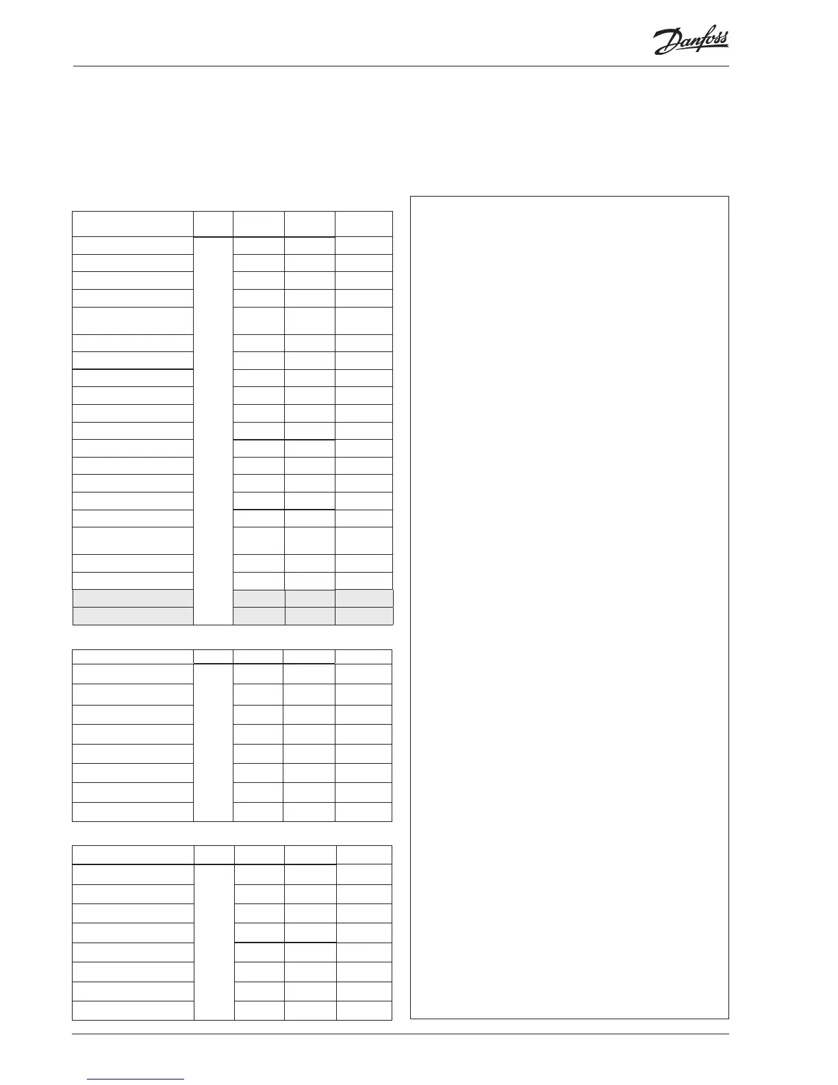
Decide during planning which function is to be connected and
where this will be.
1. Connect input and outputs
Here are the tables for the example:
Mounting and wiring - continued
The function of the switch functions can be seen in the last column.
There are AKS 32 pressure transmitters for several pressure ranges.
Here there are two dierent ones. One up to 12 bar and one up to 34 bar.
Signal Module Point
Terminal
Signal type /
Active at
Brine return temperature S3
1
1 (AI 1) 1 - 2
Pt 1000
Brine supply temperature S4
2 (AI 2) 3 - 4
Pt 1000
Consumption limitation
3 (AI 3) 5 - 6
Closed
Pump ow switch
4 (AI 4) 7 - 8
Open
Thermostat sensor in plant
room - Saux1
5 (AI 5) 9 - 10
Pt 1000
External main switch
6 (AI 6) 11 - 12
Closed
Outdoor temperature - Sc3
7 (AI 7) 13 - 14
Pt 1000
Discharge gas temperature - Sd
8 (AI 8) 19 - 20
Pt 1000
Suction gas temperature - Ss
9 (AI 9) 21 - 22
Pt 1000
Suction pressure - P0
10 (AI 10) 23 - 24
AKS32-12
Condenser pressure - Pc
11 (AI 11) 25 - 26
AKS32-34
Compressor 1 / VSD
12 (DO 1) 31 - 32
ON
Compressor 2
13 (DO 2) 33 - 34
ON
Compressor 3
14 (DO 3) 35 - 36
ON
Compressor 4
15 (DO 4) 37 - 38
ON
16 (DO 5) 39-40-41
Liquid injec. in heat ex-
changer
17 (DO6) 42-43-44
ON
Pump 1
18 (DO7) 45-46-47
ON
Pump 2
19 (DO8) 48-49-50
ON
Speed control of compressors
24 -
0-10 V
25 -
Signal Module Point Terminal Active at
Fan 1
2
1 (DO 1) 25-26-27
On
Fan 2
2 (DO 2) 28-29-30
On
Fan 3
3 (DO 3) 31-32-33
On
Fan 4
4 (DO 4) 34-35-36
On
Defrost
5 (DO 5) 37-38-39
On
Fan in plant room
6 (DO 6) 40-41-42
On
Alarm
7 (DO 7) 43-44-45
O
8 (DO 8) 46-47-48
Signal Module Point Terminal Active at
Compressor 1 Gen. safety
3
1 (DI 1) 1 - 2 Open
Compressor 2 Gen. safety 2 (DI 2) 3 - 4 Open
Compressor 3 Gen. safety 3 (DI 3) 5 - 6 Open
Compressor 4 Gen. safety 4 (DI 4) 7 - 8 Open
VSD, compressor speed 5 (DI 5) 9 - 10 Open
Frost protection 6 (DI 6) 11 - 12 Open
DI alarm, Receiver level 7 (DI 7) 13 - 14 Open
8 (DI 8) 15 - 16