AK-CH 650 Capacity controller RS8ER302 © Danfoss 2016-02 43
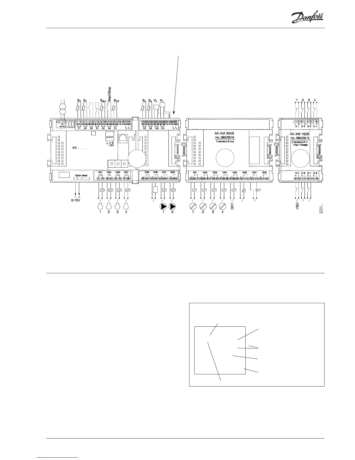
The connections for the example can be seen
here.
Mounting and wiring - continued
Frequency converter
VSD compressorspeed
Consumption limit
Room Fan
Frost protection
Receiver level alarm
Liquid injection in
heat exchanger
Pumpe ow switch
1
2
3
The screen on the pressure transmitter
cables must only be connected at the
end of the controller.
Comp. 1 Gen. safety
Comp. 2 Gen. safety
Comp. 3 Gen. safety
Comp. 4 Gen. safety
Warning
Keep signal cables separate from
cables with high voltage.
2. Connect LON communication network
The installation of the data communication must comply with
the requirements set out in document RC8AC.
3. Connect supply voltage
Is 24 V, and the supply must not be used by other controllers or
devices. The terminals must not be earthed.
4. Follow light-emitting diodes
When the supply voltage is connected the controller will go
through an internal check. The controller will be ready in just
under one minute when the light-emitting diode ”Status” starts
ashing slowly.
5. When there is a network
Set the address and activate the Service Pin.
6. The controller is now ready to be congured.
■ Power
■ Comm
■ DO1 ■ Status
■ DO2 ■ Service Tool
■ DO3 ■ LON
■ DO4
■ DO5 ■ Alarm
■ DO6
■ DO7
■ DO8 ■ Service Pin
Internal communication
between the modules:
Quick ash = error
Constantly On = error
Status on output 1-8
Slow ash = OK
Quick ash = answer from gateway
in 10 min. after network
installation
Constantly ON = error
Constantly OFF = error
Flash = active alarm/not cancelled
Constant ON = Active alarm/cancelled
External communication
Network installation