104 Capacity controller RS8ER302 © Danfoss 2016-02 AK-CH 650
Compressor application 6 – 1 x Speed + unloader
The controller can operate one speed-regulated compressor com-
bined with several capacity-regulated compressors of the same
size and with the same number of unloaders.
The advantage of this combination is that the variable part of the
speed-regulated compressor only needs to be large enough to
cover the following unload valves in order to achieve a capacity
curve without gaps.
Preconditions for using this compressor application are:
• A single speed-regulated compressor that can be of a dierent
size than the following compressors
• The capacity-regulated compressors are the same size and have
the same number of unload valves (max. 3)
• The main step on the capacity-regulated compressors are the
same size
• The main step and the unload valves can be dierent sizes, i.e.
50%, 25% and 25%.
This compressor combination can be handled in the following
coupling patterns:
• Sequential
• Cyclical
Handling the speed-regulating compressor.
For further information on the general handling of the speed-
regulated compressor, refer to section "Power pack types".
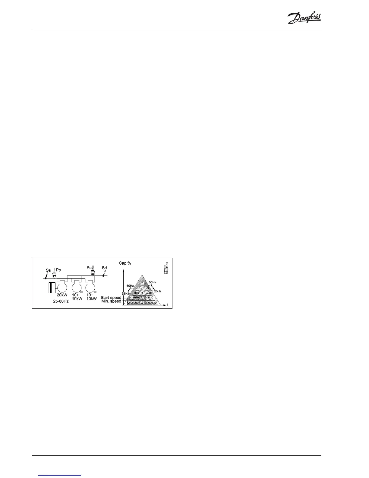
Cyclical operation - example
The speed-regulated compressor is always the rst to start and
last to stop.
The capacity-regulated compressors are cut in and cut out in ac-
cordance with the First-in-First-Out principle in order to equalise
operating hours
The speed-regulated compressor is used to ll the capacity gaps
between the unload valves/main steps.
Increasing capacity:
- The speed-regulated compressor starts when the desired
capacity matches the start speed
- The main step on the capacity-regulated compressor with
fewest operating hours (C1) is cut in when the speed-regulated
compressor runs at full speed (60 Hz)
- The unload valves are cut in gradually as the speed-regulated
compressor again reaches max. speed (60 Hz)
- The main step on the last capacity-regulated compressor (C2)
is cut in when the speed-regulated compressor again reaches
max. speed (60 Hz)
- The unload valves are cut in gradually as the speed-regulated
compressor again reaches max. speed (60 Hz)
- When the main step or unload valves are cut in, the speed is re-
duced on the speed-regulated compressor (35 Hz) is equivalent
to the capacity of the cut in capacity.
Decreasing capacity:
- The capacity-regulated compressor with the most operating
hours (C2) cuts out an unload valve when the speed-regulated
compressor has reached min. speed (25 Hz)
- When the speed-regulated compressor again reaches min.
speed (25 Hz), the unload valve is cut out on the next capacity-
regulated compressor (C3)
- When the speed-regulated compressor again reaches min.
speed (25 Hz), the main step is cut out on the capacity-regulat-
ed compressor with the most operating hours (C2)
- When the speed-regulated compressor again reaches min.
speed (25 Hz), the main step is cut out on the last capacity-
regulated compressor (C3)
- The speed-regulated compressor is the last compressor that is
cut out when the conditions for this are fullled
- When the main step or unload valves are cut out, the speed of
the speed-regulated compressor increases (50 Hz) to equiva-
lent to the cut out capacity
 Loading...